


ZENITH CARBURETTERS SERVICE BULLETIN
SERIES VN

The VN range of carburetters are all downdraught types. Their design incorporates an automatic strangler linked with the throttle to provide a fast-idle, a depression-operated economy device and a mechanically-operated accelerating pump. Models in the series with the addition of another letter "N" in the suffix letters i.e. 30 VNN indicates the accelerating pump and the economy device are not incorporated having been determined to be unnecessary on the particular application.
The fuel level is controlled by a lever-type float mechanism, and a particular feature of the series is the manner in which all the jets are centrally mounted in the specially-designed emulsion block. Other special models with a different suffix letter following the letters VN signify special features. Those in current production at the date of this leaflet are as follows :-
- VNR The letter R indicates the carburetter has incorporated a velocity governor and is fitted on certain makes and models of commercial vehicles. The operation and adjustment of the governor is the subject of a further leaflet SB.204.
- VNT The letter T indicates the model has a thermostatically operated choke or strangler for cold starting. The operation of the thermostat and the adjustment is described on leaflet SB.209.
- VNP The significance of the letter P indicates the model has the accelerating pump feature but not the economy device.
There are certain variations to the circuits in different sizes of VN series carburetters as will be seen by reference to the section drawings on page 2 of the leaflet and in the size 42 VN there is the additional auxiliary jet No. 29 to supplement output of the main and compensating jets at high engine speeds when depression in the passage to the air bleed 27 is high. This auxiliary jet is also used in some size 32 VN models. (In certain later 42 VN's the auxiliary jet is not used and a calibrated hole is drilled in the emulsion block).
Adjustments
There are three principal adjustments provided in these carburetters. They are:-
- (a) The volume control screw 21, for the regulation of the idling mixture.
- (b) The throttle stop screw 16, to control the idling speed.
- (c) The strangler/throttle interconnection, to adjust the amount the throttle opens when the strangler is closed for cold starting.
Operation
These will be referred to more fully later in the text. The petrol inlet 8 is at the top of the float chamber. From here, fuel passes into the float chamber via the needle seating 11, where the flow is controlled by the needle 9 and the float 10. As the petrol level rises the float lifts and, by means of the float arm and needle, closes the needle seating when the correct level has been attained. When the engine is running, petrol is drawn from the float chamber; the float descends and more fuel is then admitted through the needle seating. By this means, the correct level is automatically maintained the whole of the time the carburetter is in action.
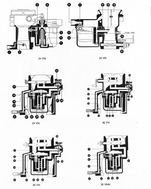
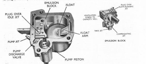
The petrol then passes to the emulsion block 13, which houses the main, compensating and slow-running jets (25, 24 & 19), together with the two calibrated ventilation plugs 18 and 27, which act respectively as air bleeds to the slow-running jet and the capacity well.
Starting from cold
When the dashboard control is pulled out, it operates the cam lever at the side of the carburetter. This allows the spring-loaded strangler flap 14 to close; simultaneously, the interconnection rod between the cam lever and throttle spindle automatically cracks the throttle open sufficiently to give a good fast-idle. With the ignition switched on (but without touching the accelerator pedal) the engine is turned over either by the starter or by hand. Immediately it fires the speed will tend to build up, and the increased depression thus created will open the strangler flap, admitting more air and consequently weakening the mixture. While the strangler remains closed the vehicle may, if desired, be driven away, but it should be gradually released as the engine attains its normal working temperature.
Idling
When the throttle 2 is in the idling position the mixture is supplied by the slow-running jet 19, which obtains its fuel from the metered side of the main jet 25 (at the base of the emulsion block) through the calibrated restriction 23. This fuel is partly emulsified by air supplied by the air bleed hole 17 in the air intake, and the resulting mixture is then drawn down the vertical channel to the idle hole 22, which is controlled by the volume control screw 21. A secondary air bleed 18 is provided over the slow running jet. Although alternative sizes can be provided for this, it is recommended that no change be made under normal circumstances.
Adjustments to the idling are made by both the throttle stop screw and the volume control screw (16 & 21 respectively). When screwed inwards, the throttle stop screw 16 opens the throttle and increases the engine speed. When turned in the reverse direction, the speed diminishes.
The quality of the idling mixture is controlled by the idle jet 19 and the air bleeds 17 & 18. That at 18 is a variable, as already mentioned, but the bleed 17 is drilled in the carburetter casting itself and is not intended to be altered. The quantity of idling mixture is regulated by the screw 21. This is situated at the edge of the carburetter flange, on the engine side of the throttle, and has a conical tip which permits a greater or less amount of mixture to be inspired by the engine. Contrary to the more usual "air-regulation" type of control used in many Zenith carburetters, with the volume control system, as used here, the screw should be turned inwards to weaken the mixture, and unscrewed to enrich it.
The two small holes 20 at the edge of the throttle communicate with the idle channel. Their function is to aid the transfer of the fuel supply at low throttle openings, and to furnish a smooth and progressive action during those periods; they are consequently known as "progression" holes. They are not adjustable, and must not be tampered with.
As the throttle continues to open, the engine depression at the beak 13 of the emulsion block will draw fuel from the capacity well and the channels above the main and compensating jets. At the same time, air will be admitted by the full-throttle air bleed 26 (which remains permanently open) and also sometimes by the larger part-throttle air bleed 27, which is controlled by the economy diaphragm valve 28. The resulting mixture of air and fuel will be drawn into the main jet channel, thence through the choke tube 15, past the throttle 2 and into the inlet manifold.
Gradually, as the petrol level drops, a number of small holes in the side of the main jet channel will be exposed. These will admit more air, emulsifying the mixture which, when it arrives at the emulsion block tip 13, will be still further atomised as it meets the stream of air being drawn through the choke tube 15. In certain sizes notably the 42 VN and the 32 VN there is incorporated in the main circuit the auxiliary jet 29 which obtains its feed direct from the float chamber via the vertical passage immediately below the jet. As with the main and compensating jets the size of this auxiliary jet is a variable and the size fitted as standard is that needed to supplement output of the main and compensating jets at high engine speeds to provide correct fuel air ratio which will give best power output as decided from mixture loops that are taken at all speeds and loads for a particular make and model of engine. It has been found advantageous, in certain models, to embody a calibrated air bleed in the emulsion block, over the main jet channel; similarly, in some carburetters the float chambers are vented to the interior of the air intake, as indicated at 12, but in others they are vented externally.
Economy device
At the side of the carburetter is a small casting attached by three screws. Inside is a diaphragm valve 28, which is normally held in a flexed condition by a compression spring. In the same compartment as the spring, a small hole gives direct communication with the engine side of the throttle through internal channels. Under part-throttle cruising conditions, etc., the manifold depression is high. This depression (or "suction") is imposed on the spring loaded side of the diaphragm, thereby lifting the valve from its seat and increasing the ventilation (via the part-throttle air bleed 27) to the jets, thus weakening the mixture. When the depression in the manifold is low, the valve remains on its seating because of the spring. The only air supply, therefore, to the jets is through the permanent restriction 26. The action of the economy device is entirely automatic, and is controlled by the demands of the engine.
Accelerating pump
The purpose of this is to prevent any hesitation in accelerating that might otherwise occur when a carburetter is adjusted to provide the leanest mixture at part-throttle cruising. To obtain economical running at such speeds, a controlled and metered supply of fuel is required when the throttle is suddenly opened, and this is supplied by the accelerating pump. When the pump piston 5 is at the top of its stroke, the cylinder is charged with fuel admitted from the float chamber through the non-return inlet valve 7. Upon the throttle being opened, the piston is forced down by the throttle linkage and discharges a stream of petrol through the discharge valve 3 and the horizontal pump jet into the airstream. It is returned to the charged position by the spring 6, ready for the next stroke.
The travel of the piston may be varied as required, giving a short stroke for summer use and a long stroke for winter. A small block 4 with two vertical ears is loosely fitted to the pump rod, being held in a recess over the float chamber by a light spring. This block may be arranged in two positions. With the taller ear directly beneath the pump lever, the short ("summer") stroke will be given. By lifting the block slightly and turning it through 180°, so that the shorter ear is under the pump lever (as shown in the diagram), the longer or "winter" stroke will be provided. A further feature of the pump mechanism is that the pump lever is articulated, the two portions being linked by a tension spring. This fulfils two purposes; it provides a follow-up motion to the pump if the throttle is opened suddenly, and secondly, it permits changing over from the short to the long stroke, or vice-versa, without any further alterations to the carburetter.
Automatic ignition-advance control
A connection 1 is provided at the carburetter flange for the automatic ignition-advance control. The small hole, where it breaks into the throttle bore, is very carefully drilled both for size and position, and should on no account be tampered with.
General
To remove the float chamber extract the four screws in the float chamber cover and withdraw the float chamber horizontally for about an inch, when it will drop into the hand. For access to the jets, lift the float arm and float from the float chamber and take out the two screws holding the emulsion block; this may then be removed. The main and compensating jets will be found in the base of the block. They may be identified by the size of their threads, that of the main jet being the larger. It should be noted that these two jets are cadmium plated, in order to distinguish them from other jets of similar size and shape but which have a plain brass finish. Although the two types appear to be identical, their flow characteristics are entirely different, hence it is important that plated main and compensating jets only are used in this series of carburetters. No washers are required when replacing them.
When cleaning jets, swill them thoroughly in clean petrol or blow out with air pressure. On no account use anything that is likely to damage the calibrations, such as needles, broaches, etc. Periodically check all the various screws, nuts, etc., for tightness. To prevent possible damage to the float, always remove it before cleaning the carburetter with compressed air. When replacing the block, see that the gasket is in position and is undamaged, and that the securing screws are screwed up tightly. It will be noticed that both the float and the float arm bear the word "top"; these should be uppermost when reassembled.
If the petrol level is high in the float chamber, the float arm should be bent downwards slightly, after removing the float pin: if low, bent up. As the float may easily be damaged, great care must be taken in either of these operations.
Should the strangler/throttle interconnection be disturbed at any time, it may be restored by opening the throttle a definite amount by means of the throttle stop screw. This measurement is given in the setting table for the car concerned under the heading of "interconnection setting", and is reckoned by the number of half-turns (i.e., 180°) of the stop screw from the fully-closed position of the throttle when the strangler is shut. Before re-setting the interconnection, it is advisable to note the number of half-turns to which the stop screw was adjusted for idling, so that it may be reset correctly after adjusting and clamping the interconnection rod.
Adjustments
A number of variables are incorporated in the VN series of carburetters which enable the instrument to be tuned to provide correct fuel/air ratio at all points in the range of throttle movement, and for all speeds and loads. In those instances where the VN carburetter is fitted as initial equipment on a standard make and model of engine, it will be appreciated that the sizes of the jets and other variables in the instrument have been decided only after most lengthy tests, both on the bench and on the road, by our engineers working in collaboration with the Experimental and Road Test Department at the vehicle manufacturers. In such cases, we recommend that no changes should be made to these standard settings without first making a careful investigation of other engine factors, such as ignition, valve tappet adjustments, etc.
Unless otherwise stated, all the jets and air bleeds used in this carburetter are calibrated in units of hundredths of a millimetre. Main, compensating, slow-running and pump jets are normally available in steps of five units, and air bleeds in ten. In all cases, a higher number indicates a larger calibration, and therefore a jet stamped 105 is the next size smaller than one marked 110. Half-size main and compensating jets can be supplied to order for final tuning, one stamped 97 being midway between 95 and 100. Choke tubes have their sizes marked inside, the number indicating the diameter of the smallest bore in millimetres. Variations are in steps of one millimetre, and half-sizes are not supplied.
Altitude
The obvious exception to the above comment on altering the standard setting will arise in those cases where the vehicle is being operated at heights in excess of 5,000 feet. Where it is consistently used on roads at these altitudes some reduction in sizes is necessary, to maintain the correct fuel/air ratio at the rarefied atmosphere. Below we detail recommended changes to main and compensating jets for different altitudes.
| Altitude | Main jet | Compensating jet |
|---|---|---|
| 5,000 to 7,000 ft. | 1/2 size smaller | 1/2 size smaller |
| 7,000 to 10,000 ft. | 1 size smaller | 1 size smaller |
| 10,000 to 15,000 ft. | 2 sizes smaller | 1 size smaller |
While no change is specified for altitudes up to 5,000 feet, in cases where an owner is more concerned with economy than performance it would be worth trying the smaller main jet, when the altitude exceeds 3,500 feet. It must be made clear that the foregoing suggested changes will apply only in those instances where the vehicle operates consistently at altitude; no change need be made in a run where the car climbs to a few thousand feet, then drops down again to below 2,000 feet or thereabouts as, for instance, in a journey over the European Alps.
Further Variables
Choke Tube
The size will determine the weight of charge inspired by the engine; that usually decided upon is the smallest that will ensure the maximum power required.
Main Jet
As in most models of the Zenith carburetter the mixture at speeds above idling is provided by two jets, the main jet and the compensating jet. In the VN series both of these feed simultaneously into the beak or outlet of the emulsion block, which protrudes into the choke tube at its smallest diameter. The main jet will influence power and speed; when the drilling or passage above this jet is exhausted of fuel, the output will be related to the depression existing in the choke tube and then, in turn, to that in the main passage of the emulsion block.
Compensating Jet
As already mentioned in reference to the main jet, the output of the compensating jet is complementary to that of the main jet, both feeding into the main channel of the emulsion block. The head of the channel in which the compensating jet screws is ventilated to the atmosphere by means of the main air bleed, while the petrol and air flow from the compensating jet is through the restriction near the base of the drilling in which the compensating jet screws. Thus, when petrol above the compensating jet is exhausted on acceleration, an emulsion of petrol and air will be drawn through this restriction into the main passage of the emulsion block. As in the case of the main jet, the compensating jet will feed petrol at all times (other than idling) to the main outlet of the emulsion block, and consequently any variation to the size of this jet will have an influence on mixture strength throughout the throttle range. It is therefore the combined output of the main and compensating jets that will provide the mixture strength to give the best performance of which the motor is capable. Variations to the size of the compensating jet will not have so great an influence on mixture strength as will an alteration to the main jet.
The auxiliary jet used in some models is in operation at certain speeds only and supplements the flow of the main and compensating jets. Variations to the size of this jet will affect the power and speed and if too large a size is used this would waste petrol without increase to maximum power.
Slow-running Jet
Its name indicates the purpose of this jet, which has a calibrated hole and meters the petrol to both the slow-running hole on the engine side of the throttle, and to the two small "progression" holes at the throttle edge. Half-size slow running jets are unnecessary, as the volume control screw in the throttle barrel enables the strength of the mixture to be regulated to suit a particular engine. It is only in exceptional cases that it may be necessary to alter the size of the jet from that fitted by the car manufacturers.
Slow-running air bleed
This bleed screws into the emulsion block immediately over the slow-running jet, and usually has a calibrated hole which determines the degree of ventilation to the slow-running jet. In some instances it is undrilled. Fitting a larger air bleed will weaken the slow-running mixture by reducing the depression on the slow-running jet.
Main air bleed
This screws into the side of the emulsion block, and controls the ventilation to the compensating jet and also to the three small cross channels drilled into the main passage of the emulsion block, just above the main jet. Increasing the ventilation by fitting a larger air bleed will, of course, weaken the mixture by reducing the depression on the main and compensating jets. By variations to the main air bleed, it is possible to alter the mixture ratio between low and high speeds at part and full throttle. Any alteration to the size of the bleed will affect the mixture strength over the whole speed range, but will have a greater influence at high speeds, when the depression in the waist of the choke tube is at its maximum. As already explained in the notes on the operation of the carburetter, the flow of air to the main air bleed is controlled by the diaphragm in the economy device; thus, when the diaphragm valve closes the main ventilation hole, the flow of air to the main air bleed is restricted by having to pass through the small fixed orifice 26.
Pump Jet
This jet governs the amount of petrol injected into the choke tube when the accelerating pump (which is interconnected with the throttle) is depressed. Apart from possible variations to the size of the pump jet, the stroke of the pump piston can be altered by changing the position of the block 4, as already referred to in the descriptive notes. In hot weather, or in a country where the average day temperature is appreciably higher than in the United Kingdom, it will usually be found possible to employ the short pump stroke without affecting acceleration adversely. On the other hand, during severe weather, or in a colder climate, it will be found an advantage to use the maximum stroke. Either adjustment may quickly be made when required. As mentioned in the opening paragraphs of this leaflet the models VNN do not have this feature. Where an engine has the VNN as initial equipment it has been determined the pump feature is not needed and there would be no advantage in changing to the VN having the accelerating pump.
Interconnection for Cold Starting
The degree of throttle opening when the strangler closes may be varied between certain limits. A rod secured by a screw in the strangler lever swivel enables this adjustment to be altered.
Petrol level
This is set at the factory 18mm. (23/32") down from the top edge of the float chamber at a pressure of 2 1/2 lb. per sq. inch. It should be explained that this level is that which should result when the float chamber is in position on the carburetter, with the float arm holding the needle closed against the pressure of the petrol in the fuel line. When the float chamber is removed, however, the level drops, as the float will rise when freed. In these circumstances, the surface of the petrol should be 22.5 mm. (7/8") below the top face of the float chamber if the float is left in position. Alternatively, if the float is extracted, the level should fall to 33mm. (1 5/16") below the top face. Bending the float arm down will lower the level; bending it up will raise it, as previously explained. Variations to the thickness of the washer beneath the needle and seating will also alter the level. (The above levels refer to carburetters having metal floats. In those models which have nylon floats the surface of the petrol with the float in position should be 26-27 m.m. (approx. 1") below the top face of the float chamber.)
Needle valves and seatings
These are calibrated in millimetres, the size being stamped on one of the flats of the hexagon. This size depends on the fuel pump pressure and the capacity and power of the engine.
General Notes
In addition to the foregoing jets, air bleeds, etc., which could, where necessary, be changed after the carburetter is in service, there are many drillings in the carburetter which can be varied during manufacture and are used in tuning the carburetter to an engine. It will therefore be understood the design is such as to enable the carburetter to be tailored to the requirements of the particular engine on which it is fitted. On the other hand, once the sizes of the different variables have been determined the mixture strength at various speeds and loads will remain constant, provided the jets and passages in the carburetter are clean and the mechanical condition of the instrument is sound.
In any investigation of suspected faulty carburation, first of all check through the instrument to ensure the specification, which includes choke tube, jet and air bleed sizes, is correct for the particular application. Whilst it is important to ensure that jets have the right numbers stamped on them, the possibility should not be overlooked that a jet may have been tampered with, or careless cleaning has affected the flow of petrol or air through a jet or air bleed. If, therefore there is any indication that any of these have been interfered with, a new part of the correct size should be fitted. Whilst a general check of the carburetter is advisable in the investigation of any complaint, we detail below, under specific headings, points that have a bearing on the particular trouble.
Difficult Starting from Cold
Make sure there is petrol in the float chamber, and that petrol from the fuel pump flows through the needle seating within a few seconds of rotating the engine by the starter, or by operation of the hand primer on the fuel pump. Cases are encountered where sediment or gum cause the needle to stick on its seating, thus preventing the entry of fresh petrol when attempting to start. This will explain difficult starting, as petrol remaining in the float chamber overnight may have evaporated after the car has been standing for several hours. If a sticking needle is suspected, remove the float chamber and operate the needle with the finger. Any tendency for the needle to remain closed can usually be overcome by rinsing the needle and seating assembly in methylated spirit. This will dissolve sediment or gum deposit.
Ensure that the strangler flap in the air intake closes completely when the strangler control on the dash is operated. From examination of the choke control on the carburetter it will be seen there is no mechanical connection between the strangler control wire and the spindle on which the choke flap is fitted. Movement of a cam lever on the side of the air intake permits the spring loading of the strangler spindle and arm to close the flap in the air intake: therefore undue friction by reason of a bent strangler spindle, carboned-up bearings or a broken spring would explain non-closure of the flap when the choke control is out. Removal of the air-cleaner connection will enable this to be easily checked.
The interconnection between the strangler lever and the throttle should ensure that the latter opens beyond the normal slow-running position, when the strangler is fully closed. The setting for a particular engine includes the amount the throttle should open when the strangler is shut. The measurement given is the gap between the edge of the throttle and the side wall of the throttle bore (on the slow-running outlet side), but it is also translated into half-turns of the throttle stop screw, from the point at which the screw commences to open the throttle from the dead-shut position. If the foregoing points have been checked, and ignition and engine generally are in order, a small increase in the extent the throttle opens when the strangler is closed will usually prove effective.
Difficult starting when engine is hot
This trouble is caused by an over-rich mixture and can be a source of annoyance, particularly in hot climates, but as the VN series carburetter is of non-percolating design no trouble should be encountered, provided the carburetter is in good condition and the fuel pump pressure is not excessive. If this fault is encountered, first ensure that the needle and seating fitted are clean and the seating is of the correct size. Having cleaned the assembly replace it with the correct washer, ensuring it is screwed tightly in position. While the float chamber is off examine the float to ensure it is not punctured, and see that the float arm is neither damaged nor bent. A new needle and seating of the size specified will eliminate the possibility of the assembly being worn and no longer able to withstand normal fuel pump pressure. Where it is found that petrol floods into the manifold from the beak of the emulsion block within seconds of switching off the motor in spite of fitting a new needle and seating, check the fuel pump pressure, and if necessary have it reduced to prevent the internal flooding which would explain difficulty in hot starting. Generally one can start the motor by gently opening the throttle to the fully or near-fully open position, then rotating the engine by the starter with the ignition switched off to clear the over-rich condition.
Erratic Slow-running or Stalling on Deceleration
Make certain the slow-running jet is clean, also ensure that the feed hole to the channel in which the jet screws is free. The best method of checking this is to remove the slow-running and compensating jets, then insert the nozzle of a syringe filled with petrol into the hole from which the slow-running jet has been removed; on operating the syringe, petrol should flow from the hole from which the compensating jet has been extracted. It is also necessary to ensure that the slow-running air bleed, where one is provided, is clear and fully tightened, as any air leakage down the thread of this will affect the slow-running mixture. Check to make certain that the slow-running outlet hole and the progression hole or holes in the throttle barrel are clear, and not carboned up to restrict the orifice. Remove the volume control screw to make sure the tapered end is in good condition. If it has been screwed down hard into the slow-running hole several times, a parallel portion will have been formed on the taper; this will render abortive any attempt to adjust the screw, which should be replaced with a new one. Make certain the spring under the head of the screw effectively spring-loads the screw, to prevent it vibrating out of position when set.
The degree of throttle opening will determine the speed of slow-running, while the adjustment of the volume control screw will vary the mixture strength. Set the former to give a reasonable idling speed (usually in the order of 500 r.p.m.) then adjust the volume control screw so that at the speed as set by the throttle stop screw the engine will idle evenly, with no tendency to stall on snap closure of the throttle. Also make certain that, as the throttle is opened slowly from the idle position onto the progression holes, there is clean progressive acceleration of the speed of the engine. Having set the volume control screw, it may be necessary to re-adjust the throttle stop screw slightly to give a satisfactory idle speed. Stalling of the engine is usually due to the idle speed being set too slow, or the mixture too lean. It is of course essential that the foregoing adjustments are made when the engine is at normal working temperature. While the motor is cool during the warming-up period, extension of the strangler control will provide the wider throttle opening that will be necessary to prevent the motor stalling, due to the fact that the oil in the crankcase is thicker.
Excessive Fuel Consumption
Having checked to ensure the carburetter has the standard setting of jets and air bleeds fitted, make certain that all holes and passages in the carburetter are clear. See that the strangler flap in the air intake opens completely when the dash control is released or pushed in. Dismantle the economy device to make sure the diaphragm material is intact, and is in good condition, also that the gaskets (one each side of the diaphragm) are in position and are in good condition. If a replacement diaphragm is needed it is always best to fit new gaskets and a new spring as the tension of the spring is vital to the correct operation of the economy diaphragm. When re-assembling the economy diaphragm, etc., see that the spring beneath the cover is in position and is located squarely in the recess of the metal cup in the centre of the diaphragm. Take care to tighten evenly and fully the screws which secure the cover. Any leakage at the joint will affect the degree of depression necessary to overcome the spring tension which normally holds the diaphragm down in the closed position.
Remove the ball valve that screws into the top face of the emulsion block to make certain the ball moves up and down quite freely, and will drop by its own weight. Sediment or gum could explain the ball sticking on the upper seating in this event petrol will issue from the pump jet at all times and affect consumption adversely. Usually any tendency for the ball to stick can be overcome by washing the assembly in methylated spirit. It will be appreciated that when the ball drops, any depression over the pump jet will merely admit a limited volume of air from the uncovered air bleed at the top of the valve. It will be seen there are no joints below the petrol level in the float chamber from which leakage can occur; it is, however, necessary to ensure that the gasket between the emulsion block and the inside wall of the float chamber is in good condition. Also that the screws securing the block are tightened evenly and fully to prevent any possibility of leakage around the hole through which the beak of the block protrudes.
Poor Acceleration
Check that the pump piston moves freely in its cylinder, and returns to the upper position by the spring fitted beneath the piston. Having removed the piston to ensure the cylinder is clean, extract the ball valve in the base of the cylinder and wash it thoroughly in clean petrol or methylated spirit. This will ensure that the non-return valve will close effectively on the downward movement of the pump piston. Remove the pump jet to ensure it is perfectly clear, and will give an unbroken stream of petrol from the orifice when the pump piston is pushed down and the float chamber contains petrol. If the pump link is in the short or the midway position, try the linkage in the hole which gives the maximum length of piston travel, or turn the pump block to provide the maximum stroke. Dismantle the economy device to ensure the diaphragm material is sound, as it will be appreciated that on snap acceleration the release of the depression on the engine side of the throttle which previously will have held back the diaphragm against the compression of the spring will result in the valve closing the main air ventilation to the jets. This temporary closure of the diaphragm valve will result in faster emptying of the reserve of petrol in the passages in the emulsion block above the main and compensating jets, which supplements the petrol from the pump jet. Larger pump jets are available to meet special conditions. In time, wear of the carburetter will result in reduced output from the pump and affect acceleration and slow-running adversely. Flat spots or hesitation on progressive opening can generally be eliminated by careful adjustment of the slow-running mixture, after making certain the progression holes in the throttle barrel are clear.
Loss of Power
Make certain that all jets and passages in the emulsion block are clear, and that the throttle is opening fully. Larger main and compensating jets may be tried to see if increasing the strength of the mixture will improve maximum speed and power. In cases where an engine has been modified with a view to increasing the power output, a larger choke tube with correspondingly larger jets should be tried. If we are advised of modifications made to an engine, we can usually suggest an alternative setting which will serve as a basis for commencing tests to tune the carburetter to suit the altered or modified engine. These remarks apply equally to conversions to twin or multiple carburetters, and we shall be pleased to pass on to owners the benefit of our experience on similar installations.
Parts lists for this carburetter can be supplied on application; please give name and type of car concerned. In any query, always quote the reference letter and figures stamped on the carburetter.