


ZENITH CARBURETTERS
SERVICE BULLETIN
SERIES TC, TC-2, TCA
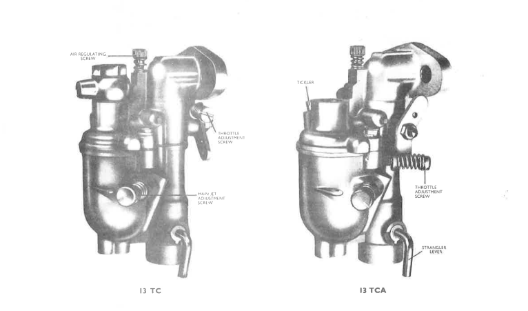
The 13 TC range of carburetters is a series of vertical instruments of very simple and compact design, for use on small petrol engines up to about 200 c.c. capacity. They have a high non-flooding angle in all directions; they are ideal for agricultural, marine and general industrial equipment (including the power units of motor-assisted cycles), and perform equally successfully on two-stroke or four-stroke engines.
The carburetters can be supplied in three different versions, the principal variation being in the operation of the throttle. They are:
| Type | Position of throttle spindle | Position of throttle lever | Throttle opening (looking on face of lever) |
|---|---|---|---|
| 13 TC | At right-angles to face of engine flange | Below flange | Anti-clockwise |
| 13 TC-2 | At right-angles to face of engine flange | Below flange | Clockwise |
| 13 TCA | Parallel to face of engine flange | On same side as main jet adjustment screw | Anti-clockwise |
Each carburetter consists of two units, the principal portions of which are diecastings. The upper portion (or throttle body) incorporates the right-angled bend, together with the fixing flange which bolts directly on to the cylinder inlet port; the lower unit consists of the float chamber (or bowl) and the air intake.
The choke tube is cast integrally as part of the latter, and cannot therefore be removed or replaced as a separate item. Bowls with 9.5 mm., 11 mm. or 12 mm. choke tubes are available. The diameter of the throttle bore outlet at the flange is 13 mm. (.512 in.).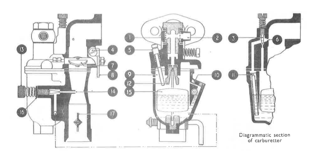
Operation
Fuel enters the carburetter through the banjo fitting (2) at the top of the bowl cover. It is filtered by the wire-mesh screen (1), then passes through the needle seating (12) into the bowl. As the petrol rises it lifts the combined float and needle (15), thus cutting off further supplies when the correct level is reached. (It is not intended that this level should be permanently altered in any way.)
The tickler (5) is provided so that the float may be depressed to raise the level temporarily, for easy starting from cold. A small hole is drilled in the side of the bowl, just above the petrol level, to prevent excessive flooding. A small drain cock can be fitted (to order) at the base of the bowl, if required, for carburetters operating on T.V.O.
Starting from Cold
The necessary rich mixture required for starting is supplied when the strangler flap (17) is closed and the engine is turned over. The resulting depression is consequently imposed on the tube (14), providing a very rich mixture, and the engine starts and continues to run.
In very cold weather, the tickler (5) may also be used. If the engine has been switched off for a relatively short period only, it will not always be necessary to use the strangler when restarting; it may, however, be found advantageous in some cases to use the tickler to ensure an immediate fire when the engine is turned over.
Idling
When the throttle is in the idling position, fuel will be drawn up through the combined slow-running jet and dip tube (11) to the air-regulating screw (3). At this point it meets air from the inside of the bowl, and the resulting mixture is inspired by the engine through the orifice (6). The mixture is enriched by turning the screw clockwise; unscrewing it has, of course, the opposite effect.
High-speed operation
The main jet adjustment screw (13) controls the fuel flow at high engine speeds. The main jet discharge tube (14) terminates in the restricted portion of the choke tube, where the depression is at its maximum. The tapered end of the screw (13) enters the outer end of the discharge tube, thereby regulating the amount of fuel drawn into the choke tube.
The volume of petrol/air mixture inspired by the engine is controlled by the butterfly throttle (7), which in turn is operated by the throttle lever (8). The small hole (10) bleeds air from the inside of the bowl into the main-jet system, as shown. This hole should not be allowed to become choked.
ADJUSTMENTS
Idling
It is usual to set the idling speed at 600-700 r.p.m.: the throttle stop screw (4) must be turned clockwise to increase, and anti-clockwise to reduce, this. Smooth idling is ensured by careful adjustment of the air-regulating screw (3), the head of which is drilled for a locking wire.
Should difficulty be found in obtaining satisfactory idling, check that the gasket between the barrel and the bowl is in good condition, and that the face of the attachment flange on the barrel is perfectly flat. A thin gasket should always be used at this flange joint.
Main jet
The main jet screw (13) is set by the engine manufacturer, and the setting should not be changed without good reason. This adjustment is always sensitive on small engines, consequently it should not be altered more than one-eighth of a complete turn at a time until the effect has been carefully noted. (The shallow notch in the head is provided solely as a mark to indicate the position of the screw.)
Always regulate the screw with the engine under load, at normal full speed with the throttle wide open: it is not satisfactory to adjust the main jet when the engine is running light on the speed governor, with the throttle nearly closed.
Turning the screw (13) clockwise will reduce the fuel flow, therefore weakening the mixture supplied to the engine. Turning it anti-clockwise will increase the flow and provide a richer mixture. Do not force the screw into its seating as this will damage the taper, thereby making correct adjustment extremely difficult.
If the setting is too weak, it will result in lack of power and possibly overheating of the cylinder, together with poor pick-up, or cutting-out when the load is applied. Do not attempt to operate on a very lean mixture, as better performance and fuel economy will be obtained if the mixture is set for full power.
An excessively rich mixture will produce black smoke from the exhaust, and may cause rapid carbon formation in the cylinder head and on the piston crown. Carbon will also quickly form on the sparking plug points, resulting in difficult starting.
The head of the adjusting screw (13) is drilled for a locking wire, and a hole in the small lug on the bowl is provided for the other end of the wire. The washer (16) is to prevent fuel leaking from the thread of the screw.
General
Flooding may be caused by excessive engine vibration, dirt in the needle seating, a punctured float, a bent float-needle, or possibly by the tickler (5) sticking down and depressing the float. Should the flooding continue after cleaning and checking the carburetter, fit a new float and needle (15) and needle seating (12), as these parts in time are subject to wear as a result of engine vibration.
Periodically check and clean the filter gauze in the banjo fixing the petrol pipe to the carburetter.
It must be appreciated that, after years of service, the moving parts in the carburetter will inevitably wear. If the vehicle is some years old, and the carburetter is the one originally fitted, this wear which can affect all aspects of carburation can have a considerable bearing on some engine troubles. We therefore strongly recommend that, when an engine needs a major overhaul, the worn carburetter is replaced by a new unit so that the utmost benefit may be obtained when the engine is restored to its original condition.