


ZENITH CARBURETTERS
SERVICE BULLETIN
SERIES MX, MXZ
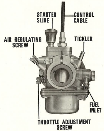
The MX and MXZ carburetters are simple, compact and highly efficient dustproof instruments, specially designed for small single and twin cylinder 2 or 4 stroke engines in applications where the engine is not governed, e.g., motor cycles, scooters, motor mowers, motor-assisted cycles, etc. They are made in various sizes, which are indicated by the diameter of the bore at the air intake measured in millimetres — thus the 11 MX has an internal diameter of 11 m.m.
Contrary to normal Zenith practice, each has a sliding instead of a butterfly throttle, and this is operated by a cable control wire in place of the more usual throttle lever.
A feature of the carburetter design is that the flooding angle is very steep, and consequently no trouble should be experienced when the engine is working on rough or sloping ground.
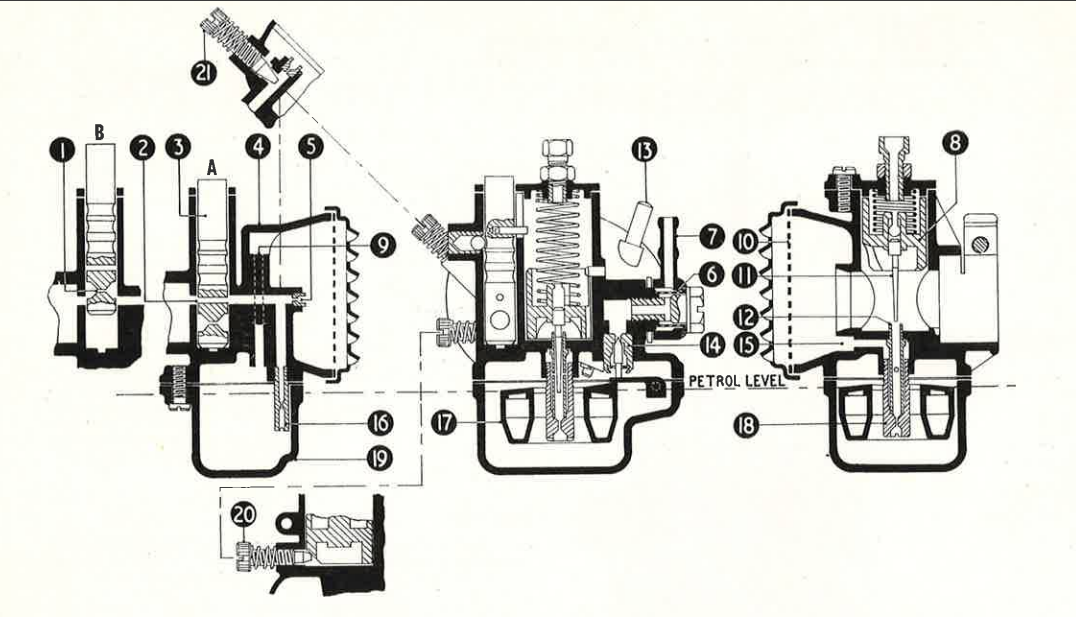
The carburetter is composed of two principal diecastings. The upper portion (or carburetter body) 4 combines the air and petrol inlets, the throttle, jets and needle valve, and the clamp for the attachment of the carburetter to the inlet stub on the engine. (In some models a tickler 13 is also fitted, to flood the carburetter for starting.) The lower portion is the float chamber (or bowl) 19, which contains the special moulded float.
Operation
Reference to the diagram overleaf will illustrate the method of operation.
Petrol enters the bowl by the elbow 7 and passes through the gauze filter 6 to the combined needle and seating 14. The latter is not removable.
A constant petrol level is ensured by a flexible tongue on the nylon float 17. As petrol enters, it rises and the tongue pushes the needle against the seating, thus preventing the admission of further fuel. Conversely, as the level drops because of the requirements of the engine, the float descends and permits the needle to open the seating once more. It is not intended that the petrol level should be altered.
Air to the float chamber is supplied via the hole 9 in the body.
Starting
Extending below the surface of the petrol in the float chamber, from the underside of the carburetter body, is the slow-running jet 16. With the throttle in the slow-running position and the slide 3 pushed right down, as at "A", petrol is lifted through the jet 16 and mixes with air from the small fixed air-bleed 5. It thus provides a suitable mixture through the hole 2, to ensure easy starting from cold without the use of a strangler.
Those models which have a tickler 13 to flood the carburetter provide the alternative method to start the engine from cold.
Idle operation
When the throttle 8 opens, the slide 3 is automatically raised to the normal slow-running position, as shown at "B," in the carburetter sizes 9, 11 and 13, but in the larger 15 and 17 models there is an intermediate position for the starter slide, and it is not until the throttle is opened to its fullest extent that the normal idle mixture is provided.
Certain later models have independent control of the starter slide to raise this to the midway or full-up position as the engine gains normal temperature.
A smaller restriction 1, of a size to supply the correct volume for idling, is consequently introduced into the circuit, and this meters the mixture (which has been emulsified by air from the air-bleed 5) supplied to the engine.
The idling speed is adjusted by the throttle adjustment screw 20. When turned clockwise, it will open the throttle wider and the engine revolutions will increase; when unscrewed, the speed will diminish.
On certain later models there is an additional adjustment screw with a locking spring to vary the strength of the slow-running mixture 21, in the section drawing. Turning the screw clockwise will enrich the mixture, anti-clockwise will weaken. This screw should be adjusted to a position that will ensure even idling with no tendency to stall.
A modified slow-running circuit was used in the 17 MXZ on certain applications notably the B.S.A. "Sunbeam" and Triumph "Tigress" Scooters. The slow-running outlet hole on the engine side of the main slide was fed direct from the main jet and there was no slow-running hole drilled in the starter slide 3.
Slides with various combinations of cross-holes are available, those with larger holes naturally providing richer mixture. However, the sizes of the slow-running jet and the holes in the slide to give the best results for any particular engine have been determined by the manufacturers only after extensive tests; we therefore recommend that they are not changed in normal circumstances.
High-speed operation
When the throttle slide 8 is raised, the tapered needle 11 will be withdrawn from the top of the emulsion tube 12, through which petrol will be drawn into the engine by the increased engine depression in the body of the carburetter. Holes through the wall of this tube admit air, which is supplied direct from the air intake via an internal channel 15 in the casting.
The fuel is metered by the main jet 18 (calibrated at its lower end) which encloses the emulsion tube 12. At full throttle this jet supplies the entire needs of the engine, as the orifice at the top of the emulsion tube will then be completely unobstructed by the needle 11; at intermediate openings the needle will restrict the flow of fuel proportionately.
General
To dismantle the carburetter bowl, first turn off the petrol supply and then remove the two screws holding the bowl in position, when it will drop into the hand.
The main jet may now be unscrewed for cleaning, if necessary, taking care not to drop or lose the emulsion tube which is a loose fit in the carburetter casting. (Ensure that when replacing the main jet the emulsion tube is inserted first, flange upwards.) The slow-running jet may also be extracted and cleaned, but the needle seating assembly is not intended to be removed.
When cleaning the jets, swill them thoroughly in clean petrol or blow out with air pressure; never use anything such as needles, wire, etc., that is likely to damage the calibrations.
Clean the petrol inlet filter 6 at regular intervals, and check that it is replaced correctly over the small boss on the body casting when refitted.
Similarly, the air-intake gauze 10 should be removed and cleaned occasionally; note that the louvres on the cover should face downwards when in position.
Jets are normally supplied in steps of two units — i.e., 50, 52, 54 etc. A higher number indicates a larger calibration; thus a jet stamped 52 is the next size smaller than one marked 54.
In the case of the slide 3, the size of the starter aperture 2 is always referred to first, and that of the slow-running orifice 1 second, when mention is made of these.
In refitting the starter slide, ensure that the pin near the top is engaged in the slot cut into the bore for the throttle slide.
Operation instructions
In the case of two-stroke engines where lubrication is by petroil, shake the engine mounting or the machine handles to ensure that the oil is well mixed with the petrol. Then open the fuel tap, and allow about seven seconds to fill the carburetter bowl.
Starting
Press down the slide 3 at the side of the cable adjuster as shown at "A" and, leaving the throttle control lever on the machine handle closed, start the engine.
In cold weather it is advisable to use the tickler 13, where fitted, for a few seconds to raise the fuel level temporarily, if difficulty is experienced in starting.
As soon as the motor is running, allow fifteen to twenty seconds for the initial warming up, then in the case of the carburetters sizes 9, 11 and 13 swing the throttle control lever to the wide-open position in order to return the slide to the slow-running position "B".
In the case of the larger 15 and 17 carburetters there is an intermediate position for the slide, and the throttle should first be opened not more than halfway to restrict the area of the starting hole in the slide which provides an enriched mixture for warming up. As soon as possible (the period depending on the day temperature) open the throttle wide to lift the slide to the full extent to get off the enriched warming up mixture.
Where the starter slide is operated independently this should be raised to the midway and then to the top position as dictated by the conditions. In the interest of economy, the slide should be raised to the top position as soon as possible.
After this, the engine, or machine, can be used normally for as long as required.
Before putting the machine away, it is advisable to turn off the fuel at the tank and allow the engine to use up all the mixture in the bowl of the carburetter. This will materially help cold starting when the engine is next required.
Maintenance
If the carburetter is fitted with a filter gauze 10, clean it by removing the two screws securing the air-intake cover and brushing when necessary. On some applications there is a separate cleaner on the intake; in such cases keep the element in this clean.
Periodically remove the bowl and clean it out thoroughly.
See that all screws and jets are tight, and that no leakage of fuel occurs from the petrol inlet connection or the joint between the carburetter body and the bowl.
When refitting the carburetter, make certain the rubber "O" ring is in position and before tightening the clamping screw push the carburetter hard against the inlet stub to compress the "O" ring thus ensuring an airtight joint. Leakage at this point will cause difficulty in adjusting idling, and could explain erratic running.
Should the throttle 8 ever be removed for any reason, care must be taken not to bend the needle 11, otherwise the operation of the carburetter may be seriously affected.
Part lists for these carburetters can be supplied on application; please give the name and type of the engine concerned. In any query, always quote the reference letter and figures stamped on the carburetter body.