


ZENITH CARBURETTERS
SERVICE BULLETIN
Series IZE, IVE AND WIAET Emission Control Features
From the fixed choke tube range of carburetters, three types of units carry the "E" suffix which denotes a carburetter adapted for emission control purposes. These are models IZE, IVE and WIAET. As regards general operation these carburetters conform to the information given in the appropriate Service Bulletins. The differences which may be found on emission control versions are as set out here.
The most critical periods for exhaust emission occur at idle and light throttle running and also on over-run with a closed throttle. Therefore most carburetter emission modifications are carried out in the circuits and components which deal with these periods of engine running.
Certain carburetters may be designated as "E" models without appearing to differ in any way from a standard carburetter. In such cases the unit has been built to special close tolerances as regards jet flow rates and the positioning and size of fixed drillings such as progression outlets. In addition, at the end of the assembly process, these carburetters are flow tested to a closer flow band tolerance than a normal non-emission unit.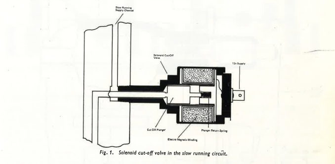
SOLENOID-SLOW-RUNNING CUT OFF
(used on some types of IVE)
On emission-controlled engines, the weak setting of the idle and light throttle mixture may cause an abnormally high idle temperature which in turn can cause the engine to auto-ignite and continue to run when the ignition is switched off.
To prevent this problem there is on certain applications, a cut-off valve installed in the slow-running circuit. As shown in Fig. I this consists of a solenoid operated valve mounted on the carburetter body. The outer casing of the valve contains an electro magnet and within this works a plunger, the nose of which extends into the slow-running mixture channel.
The electro magnet is energised whenever the ignition is switched on, whereupon the magnetic field draws out the plunger thereby opening the slow-running circuit. When the engine is switched off, the plunger moves inward under the influence of a coil spring and in doing so shuts off the slow-running circuit completely. In this way no fuel is supplied by the carburetter and this will positively stop the engine regardless of any hot spots which may be present in the combustion chambers.
Should the valve fail, it will stay permanently in the shut-off position which will cause the engine to stall at idle. The action can be checked by earthing the body of the valve when it has been unscrewed and connecting a 12 volt supply to the terminal. If the plunger does not operate, the component must be replaced.
G.7502 Price 5p Sheet Ref.: SB.219
INTERNAL/EXTERNAL VENT VALVE
(used on IZE types)
While normal "IZ" carburetters may incorporate external float chamber ventilation by means of a simple drilling and dust cap on the float chamber cover, certain "IZE" models use an internal vent channel which runs within the cover casting and breaks through into the upper part of the carburetter air intake. By virtue of this channel, any depression in the air intake is transmitted to the float chamber, therefore the carburetter is insensitive to changes in pressure in this area due for instance to a gradual increase in the air restriction caused by an air cleaner element which is progressively becoming clogged with dirt.
Mixture strength on an internally vented carburetter will remain constant under these circumstances, where on an externally vented unit gradual richening-up will occur as the element becomes choked.
One drawback of the internal layout is that on idle or when the engine is switched off when hot, fumes from the float chamber may flow via the vent channel into the air intake. Their presence will give poor exhaust emissions on an idling motor or in the case of a hot engine when switched-off, the accumulation of fumes in the air cleaner box may render re-starting difficult.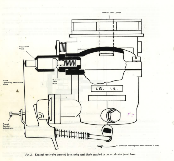
For these reasons, certain "IZE" applications use dual venting with the internal vent permanently open, whilst the external vent can be brought into or put out of action by means of a plunger type valve. An external vent valve is shown in Fig. 2 where the principle of operation can be easily understood.
The valve assembly is a press fit into a boss cast on the float chamber cover. The actual plunger protrudes from the valve body and is tensioned outwards by a coil spring. In this position air can enter or leave the float chamber via the external vent hole.
The valve is operated by means of a spring steel blade attached to the accelerator pump lever. By virtue of the action of the pump operating rod, the blade will move inwards towards the valve when the throttle is opened and this action will depress the plunger onto its seat, thereby shutting off the external vent. Therefore on idle or when the motor is switched off, the external vent will be open allowing float chamber fumes to escape harmlessly. As soon as the throttle is opened, the external vent is shut off, so that the float chamber is then under the influence of air intake depression which will prevent richening up.
The proximity of the steel blade to the plunger head is pre-set during manufacture and thereafter the tensioning screw is sealed with a dab of paint. Do not tamper with this adjustment and also during servicing take care not to distort the blade. If the adjustment has been disturbed, re-set a nominal clearance of 2 m.m. between the valve and blade, with the throttle in the normal idle position.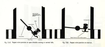
THROTTLE POPPET VALVE
(used on some IVE types)
As already mentioned, exhaust emissions experience a critical phase when the engine is on over-run, i.e., deceleration on a closed throttle. When this occurs, the sudden increase in manifold vacuum thus caused will draw into the engine all the fuel which may be clinging in a condensed form onto the manifold walls. This gives an unsatisfactory period of rich running after which, when this fuel has been used up, mixture then becomes overweak. Both of these conditions will give poor emission and this is countered by the use of a poppet valve in the throttle plate as illustrated in Fig. 3(a)(b).
This device consists of a disc and spindle mounted on the lower blade of the throttle flap. The disc is positioned on the underside of the throttle and the spindle projects through to the upper side where a coil spring is fitted to hold the disc in close contact with the throttle.
The load of the spring is chosen to hold the valve shut when the throttle is open or when it is closed on normal tick-over. On over-run however, manifold vacuum will become abnormally high and this will be sufficient to draw the valve off its seat and permit mixture to bleed through the stamped out holes in the throttle.
This will mean that manifold vacuum will be prevented from reaching a critically high level, and that the mixture bleed on over-run will maintain efficient firing of the engine until tick-over speed is reached, whereupon the valve will automatically shut as vacuum falls.
The air bleed through the throttle may cause engines so equipped to run down to idle more slowly than would be the case on a standard motor, but generally the poppet valve will operate without the vehicle driver being aware of its action. This device requires no maintenance whatsoever. Failure of the tension spring will result in a permanently high idle speed, requiring replacement of the throttle and valve assembly.
THROTTLE BY-PASS CIRCUIT
(used on IZE types)
As already mentioned, idle and light throttle running are critical periods as regards exhaust pollution and, as light throttle mixture is largely influenced by fuel output from the progression drillings, it is advantageous to have a known relationship between the position of the throttle edge at idle and the position of these drillings.
On some "IZE" models therefore the usual throttle stop screw and spring is replaced with a screw and locknut which is adjusted during manufacture to give the ideal degree of throttle opening and is thereafter locked.
To alter idle speed, it is no longer possible to slightly adjust the throttle position, and to enable idle speed adjustment to be carried out an air by-pass circuit is used, Fig. 4. In this design a channel runs from the lower choke tube area to an outlet below the throttle edge. Flow through the channel is controlled by means of a tapered adjusting screw.
Turning this component clockwise will reduce airflow thereby slowing down the idle, turning the screw anti-clockwise will increase speed. Into the outlet of this channel the idle mixture is introduced, and is controlled by a normal volume control screw.
By virtue of the position of the inlet to the air by-pass channel, this circuit will have a negligible flow when the throttle is open, as the depression in the lower choke tube area and in the throttle area will be approximately the same.
Should the throttle setting screw be tampered with, it is not possible to rediscover the ideal setting. In such cases the best course of action is to unscrew the control until the throttle is fully closed and then to screw in the set screw until just sufficient clearance exists on the throttle to prevent it jamming in the barrel in the idle position. The screw should then be locked.
OFF-IDLE ADJUSTER
(used on IVE and IZE types Fig. 5)
One other special feature of the IZE and IVE units is the progression or "off idle" adjustment which may be used along with or independently of a throttle air by-pass device. Taking the IZE as an example, a branch is taken from the slow-running supply channel leading to the progression outlets.
Into this channel is set a tapered adjusting screw which merely enables the mixture output from the progression holes to be set independently of the mixture from the slow-running hole. The adjuster is mounted within a tubular brass housing which in turn screws into the side of the carburetter main body.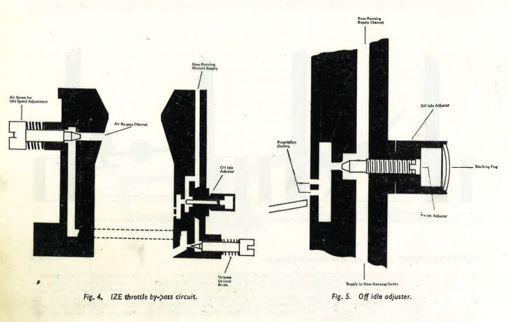
Once again this is a manufacturer's predetermined setting and, when progression mixture has been set to the optimum level, the housing is plugged to prevent access being gained to the adjuster. No attempt should be made to remove or tamper with this item.
WIAET and WIAETD TYPES
These carburetters fulfil emission control requirements by means of close tolerance production and testing and contain none of the additional circuits described above.