


ZENITH CARBURETTERS SERVICE BULLETIN
SERIES 26 V & 30 V
WORKING DESCRIPTION
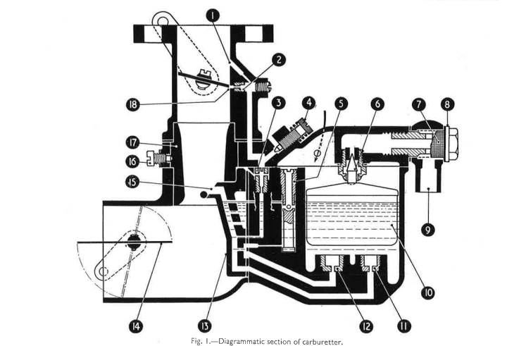
The diagram above illustrates a typical vertical model of the "V" type carburetter in cross-section, but it also applies to the horizontal and downdraught instruments for the purpose of following the course of the petrol, from its entering as a fluid until it leaves the carburetter and is drawn into the engine as a correctly proportioned mixture of petrol and air.
From the tank, petrol passes through the pipe to the union 9 of the carburetter. The flow continues through the filter 7 and the seating and needle 6 into the float chamber. Passing through the main jet 11 and compensating jet 12, petrol will flow along the passages to a common channel in the emulsion block 13, and continue to flow until the channels and the float chamber are filled to a predetermined height. The float 10 will then have lifted the needle 6 against its seating, thus preventing further petrol entering and flooding the carburetter. It has now been observed how the petrol reaches the jet and channels. The fuel will occupy the position described all the time the engine is stationary, and there is a supply of petrol.
STARTING
Special arrangements for starting are made on the "V" type carburetter. Many models have stranglers fitted, but a type is available with an automatic starting device.
Stranglers
To provide the required rich starting mixture some "V" type carburetters have a strangler flap 14 in the air intake. When the control from the dash is operated the flap closes the air intake, and upon the engine being turned over the depression is directed entirely upon the jets of the carburetter. Consequently a very rich mixture is supplied, and the engine starts readily and continues to run.
It is often advantageous to give the engine one or two turns with the strangler closed and the ignition off. Then switch on and again turn the engine over by starter or handle. Most stranglers are interconnected with the throttle so that the latter is automatically opened the right amount when the strangler is closed. If this is not so, it is recommended that for starting purposes the throttle is opened slightly by means of the hand control. The correct amount will soon be found by experiment.
Semi-automatic Strangler
This type has a flap secured by screws to the strangler spindle, having in it an opening covered by a spring diaphragm. This remains closed during the initial firing but, as the engine speed increases, because of the general thinning of oil, easing of bearings, pistons, etc., the extra depression causes the diaphragm to open. Air is thus admitted and the desired weakening effect obtained.
Fully-automatic Strangler
In this type the strangler flap is free to move on an offset spindle, and is held closed by means of a light coil spring only. When the extra depression is created after the engine has started, the tension of the spring is overcome, and the flap opens and admits air to give the necessary weakening effect.
Incidentally, in both types the varying depression causes the diaphragm or flap to pulsate and give a buzzing noise, which acts as a warning note that the strangler is in operation.
Note: It will be appreciated that even with the mixture weakening devices in full operation, the charge is still considerably richer than that normally supplied. Consequently, as the engine warms to its work, the strangler control should be released and dispensed with entirely as soon as conditions permit. Many strangler controls are provided with notches to enable the flap to be opened in stages.
Automatic Starting Device
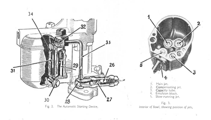
Some models of the "V" type carburetter are fitted with a starting device similar to that shown in Fig. 2. (This shows a downdraught carburetter, but exactly the same principles apply to other models.)
To start the engine from cold the automatic starting device control on the dashboard is operated, resulting in the main valve 26 being drawn off its seating to the position shown in the drawing. With the ignition switched on, the engine should now be turned over by means of the starter, ensuring at the same time the accelerator pedal is not depressed. It is essential that the throttle should not be opened beyond the normal idling position for starting purposes. When the engine is rotated with the throttle in this position, all the suction or depression created will be concentrated on the outlet 27 on the engine side of the throttle.
This depression will be concentrated at the venturi 28 and in the communication tube 33, which will result in air being drawn through the venturi, and petrol from the dip tube 31. The petrol is drawn from the dip tube through the control jet at the top. It then passes across the connection 32, down the communication tube 33, and then to the throat of the venturi 28. Here it will be met by air entering the venturi, and will be broken up to form a rich starting mixture, which will then pass into the induction pipe through the drilling 27. The sizes of the dip tube, venturi, starting jet and control jet are such that this mixture of petrol and air is correct to ensure that it will now fire and the engine continue to run.
This rich mixture is necessary for a short period only. Automatic weakening-off is ensured by air from the hole 34 mixing with petrol issuing from the starting jet 30, as soon as the fuel in the dip tube well and reserve well 29 has been exhausted. Consequently, the mixture is automatically weakened, and the engine will continue to run at a fair speed for a while without "hunting" or showing signs of an unduly rich mixture. These are ideal arrangements for starting engines from cold. A very rich mixture is only necessary for the initial firing, after which a more normal mixture is provided, which causes the engine to run at a speed that promotes rapid warming up and circulation of the lubricating oil, thereby minimising cylinder wear. At no time is neat petrol entering the engine.
MAIN CARBURETTER
With the starting device valve closed, or strangler opened, and the throttle in the idling position, the engine is now working on the main carburetter only.
The depression will be concentrated on the outlet 1 (Fig. 1) which will in turn be directed on to the slow-running jet 3. Consequently petrol will be drawn from the well beneath the jet, measured on passing through, and meet air entering at the base of the adjustment screw 4. The amount of petrol issuing from the slow-running jet is controlled by this screw.
At the throttle edge there is a further outlet 18, which breaks into the slow-running channel. Upon the throttle being opened from the idling position, this will give an additional mixture to ensure a progressive getaway from slow-running. This explains the title of "progression jet" for item 2.
Upon the throttle being opened still further, the depression will be concentrated at the beak 15 of the emulsion block, which projects into the narrowest part of the choke tube 17. This will first result in petrol being drawn from the main channel in the emulsion block, the channel beneath the slow-running jet 3, and from the well of the capacity tube 5, so that the source of petrol supply is eventually through the main and compensating jets 11 and 12.
It will be observed that the petrol in the well of the capacity tube 5 has been consumed, and as the top of the well is open to the atmosphere, petrol issuing from the compensating jet along the passage beneath is now air-bled from the atmosphere. So is the well-tried Zenith mixture compensation system maintained in this modern carburetter. As depression increases, the compensating jet supplies a weaker mixture whilst the main jet delivers more petrol. The fuel issuing through the main jet 11 will meet the emulsified petrol from the compensating jet 12 in the common channel. This will tend to break up the petrol from the main jet also, so that when the supply from both sources is eventually drawn from the emulsion block nozzle into the choke tube complete atomization is assured.
It is essential that this mixture should be distributed completely across the choke tube in all directions. To obtain this even distribution, a small circular bar has been placed across the choke at right angles to the emulsion block beak. At right angles to the nozzle (on certain models of the "V") another bar is placed, actually an extension of the screw 16 holding the choke tube (on models where this is possible), and air drawn from the intake will strike these bars and create a partial vacuum on the sides facing the engine. The petrol/air mixture leaving the emulsion block will also strike these bars and run along them to fill up the vacuum, and then proceed, evenly distributed across the choke, past the throttle valve and into the induction pipe.
It will be realised that as soon as petrol in the float chamber falls below the predetermined level the float will fall, permitting the needle 6 to drop, and more petrol will pass into the chamber through the seating.
The larger models of the "V" operate in exactly the same manner, but the jets are removed to the outside of the carburetter. The jets are underneath the bowl and are covered by removable screwed plugs. A further variation is that the float is hinged to the inside of the float chamber. Some of the larger carburetters have a pump and special economy device incorporated; these are described in a separate publication.
ADJUSTMENTS
The carburetter is delivered with a jet setting that has been found by extensive experimental work to be most suitable for the engine to which it is fitted. Consequently, very few adjustments to the carburetter should be needed. Indeed, the user will find that greater service will be obtained from the instrument if these are made only when absolutely necessary. Adjustment to the slow-running mixture is the only likely alteration, apart from an occasional cleaning of the jets, float chamber, filter gauze, etc.
When trouble is experienced with the engine, do not assume that it is always due to the carburetter. If satisfied that the instrument is completely free from dirt, do not be tempted to alter the carburetter until all other possible causes of trouble, such as sparking plugs, ignition, valves, etc., have been investigated.
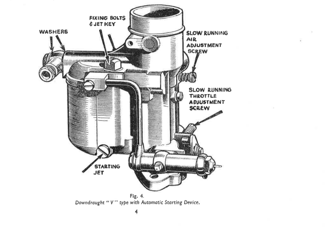
The bowl of the carburetter is removed by releasing the fixing bolts. The hand should be placed beneath the bowl during this operation, so that it will drop into the hand. (Economy note—petrol in the bowl can then be emptied back into the tank.) The jets should be removed occasionally and thoroughly cleaned. One of the fixing bolts is squared at the end to fit into the jets. When this is fitted in the squared recesses, a spanner applied to the head of the bolt will enable the jets to be unscrewed. When cleaning the jets, do not pass anything through them that is likely to damage the carefully calibrated orifices. The most satisfactory and efficient method is to blow through them, and wash them in petrol. This will remove any obstruction, and leave the jets undamaged.
The sizes of all jets in Zenith carburetters are clearly marked; the larger the jet, the greater the number.
The slow-running jet 3 is provided with a screwdriver slot for its removal. This also applies to the screw holding the capacity tube. Upon removing the screw and inverting the bowl, the capacity tube will fall out. (On many "V" type carburetters the size of capacity well is decided upon before the final casting is made; in such cases it is cored the required size and no capacity tube is required. This type is at once recognised, as the top of the well is not threaded to take the retaining screw, as are the carburetter bowls using capacity tubes.)
The emulsion block is held to the side of the bowl by three (in some cases five) screws. To remove the block, first ease the bottom screw, and then completely remove those above. The bottom screw should not be removed completely, but upon turning this in an anti-clockwise direction, it will come away from the bowl, complete with the emulsion block. Particular care should be taken not to damage the gasket beneath the block. Never use shellac or any jointing compound on this gasket. Upon replacing the block, locate the bottom screw first, and then tighten the remaining screws evenly.
The starting jet is removed from the carburetter by means of a screwdriver. This applies also to the progression jet 2, but in this case the plugging screw must be removed first, and care taken that it is replaced after inspection. Whenever possible the progression jet is combined with the plug or cover to form a complete unit. Many models of the "V" will now be found to have this combined jet and plug.
The slow running is adjusted by means of the throttle stop screw and the air regulating screw (Fig. 4). The stop screw determines the speed of the slow-running, i.e., it adjusts the throttle position for idling. To increase the slow-running speed, the stop screw must be turned in a clockwise direction. If unscrewed, a slower tick-over will result.
The richness of the slow-running mixture is adjusted by the air regulating screw. Should the engine refuse to tick-over for any length of time, or stall on deceleration, the slow-running jet may be choked, and should be cleaned. After examination, reset the slow-running by means of the throttle and air adjustment screws. If the engine is inclined to "hunt" when running slowly, the mixture is too rich, and must be weakened by turning the air regulating screw in an anti-clockwise direction. The best position for the slow-running air screw from the point of view of pick-up is within one turn of the full "home" position. Some models have an elongated taper to the screw, and in such cases the adjustments should be within three turns. A size of slow-running jet must be decided upon that will permit even tick-over with this setting of the screw, although a slight tendency to richness can often be corrected by setting the idling speed a trifle faster.
There are other factors quite apart from the carburetter that have considerable influence on the slow-running, i.e., slow-running when the engine is out of gear and the car is stationary. These factors include non-airtight joints, worn valve guides, badly seating valves, unequal tappet adjustment, ignition too far advanced, incorrect setting of sparking plug points, etc. Such details must always be taken into consideration. The carburetter only should not be suspected if slow-running is not satisfactory.
The Filter
Petrol is filtered on entering the carburetter, and the gauze 7 should be cleaned occasionally. To remove this item, unscrew the plug 8 and slide the filter from it. The gauze can then be cleaned thoroughly with petrol. When reassembling the filter, care should be taken to see that the washers on both sides of the petrol pipe connection are correctly replaced.
The Bowl
It will be seen that the jets are situated well away from the bottom of the bowl, so that any sediment will fall around and not into the jets. To keep the bowl clean, swill it out occasionally with petrol.
Acceleration
The acceleration is controlled mainly by the slow-running adjustment and the size of the compensating jet. Bad adjustment will cause a flatspot when opening up from the slow-running position, and it is often advantageous to set the slow-running mixture on the rich side to avoid this. If the engine is sluggish in picking up at slow speed, then a different size compensating jet should be tried. When the compensator is too small there is generally a long pause before the engine responds to the opening of the throttle, and spitting back may occur. If it is too large the acceleration is heavy.
Power on hills
The strength of the mixture when the engine is pulling hard at low speed is determined by the compensating jet. If the car lacks power on steep hills, experiments should be made with this jet until the required power is obtained.
Speed
Care should be taken to make sure that the lack of speed is not due to retarded ignition, an insufficient supply of petrol from the tank or pump, faulty ignition, poor compression, or to some restriction at the carburetter intake. If the loss of speed is definitely due to the carburetter, different sizes of main jets should be tried, as this jet has most influence at high speed. If no improvement is affected, no matter what size main jet is fitted, then a size larger choke tube should be employed, and the most suitable main and compensating jets found by trial.
Popping back
When the car gets away badly and popping back occurs in the carburetter when accelerating, the compensating jet is too small. If this trouble happens at irregular intervals, and the engine has little power and cannot drive the car at a high speed, the main jet is at fault and larger sizes should be tried until the explosions cease. Popping in the silencer when coasting downhill is generally a sign that the adjustment of the slow-running mixture is too weak or the slow-running jet is choked, if carburation is at fault. Popping back is very often due to defective sparking plugs or valves not closing properly.
Starting
If the starting device is working correctly, i.e., the jet is clean and the main valve opens the full extent when the dash control is operated, no starting difficulty will be experienced. This, of course, is always provided all engine factors are correct. Insufficient revs. on the starter is often the cause of difficulty in starting and may be due to a run-down accumulator, an inefficient motor or the crankcase oil being too heavy for the time of year. Plugs, too, play an important part. Make sure they are clean and dry, are the correct type for the engine, and have the specified gap at the points.
If difficulty in starting is experienced with carburetters fitted with a strangler, ensure that the strangler flap closes completely when operated from the dash. A choked slow-running jet or incorrect adjustment of the air screw will also cause bad starting. This, however, is easily remedied by removing the jet, cleaning and replacing it, and then resetting the screw. Care should be taken to see that the bowl is bolted tightly to the float chamber cover of the carburetter. Only when all these points have been investigated should the setting of the starting device be altered, if difficult starting persists.
Troublesome starting can be classified generally as follows:-
- (a) Engine fails to fire.
- (b) Engine fires but fails to run.
- (c) Engine fires and runs, but the mixture is over-rich.
(a) Engine fails to fire
The adjustments to enrich the starting mixture on this device are to the control jet and starting jet. The control jet measures the petrol flow until the fuel in the well is consumed, and thereafter affects the depression on the starting jet. First try larger starting jets, but failing improvement resort to increased sizes of control jets.
(b) Engine fires but fails to run
Over-rapid weakening-off is the fault here, and a larger starting jet should be tried to overcome the fault.
(c) Engine fires and runs, but mixture is over-rich
First try a smaller starting jet, but if this affects initial firing a smaller control jet should be fitted.
N.B. The concentration of the depression upon the starting device is most essential. Ensure, therefore, the throttle is closed to the idling position when the engine is being started.
Excessive petrol consumption
The carburetter is frequently blamed for this defect when it is actually caused by the engine being in poor condition, or by the ignition being retarded. There may be a leak in the petrol system, the brakes may be binding, or there is a restriction at the carburetter intake. Moreover, rough estimates are very misleading, and the consumption should be carefully checked over a hundred miles or so to make sure that it is really excessive.
It should be remembered that short journeys and town work mean an increased petrol consumption and that the average generally stated by the car makers is for country running over give-and-take roads with normal loads, driving at a speed of 30/35 m.p.h.
If, however, it is certain the consumption is excessive, and various adjustments to the engine have been made, then so far as the carburetter is concerned we suggest trying slightly smaller jets. First try one size smaller main and compensating jets. If this does not affect the road performance, then try even smaller jets. However, should the performance deteriorate by fitting smaller sizes in both main and compensating jets, it should be remembered that there is no relation between these two parts, and it is quite in order to alter the size of one and not the other. Consequently, the effect should then be tried of reducing one jet at a time.
If the carburetter is definitely to blame for heavy consumption, then it must be giving a mixture richer than is necessary. This can always be remedied by fitting smaller jets. If the performance suffers when such jets are used, then it is apparent that the cause of the trouble is not in the carburetter.
It should be made quite certain that the automatic starting control is working freely, and that the main valve is returning completely to its seating. If this is not so the device will remain in action, and consequently will be supplying extra fuel to that given by the main carburetter. Care must also be taken to see that the strangler flap, on carburetters to which one is fitted, is returning to the full-open position.
Heavy consumption may be caused by excessive pressure from the fuel pump. This is usually indicated by the fact that it is impossible to obtain a smooth tick-over irrespective of the position of the air screw for slow running, and also by black smoke from the exhaust. When running downhill, petrol fumes in the car will also be apparent. This may be overcome by fitting a slightly smaller needle seating to enable the needle to cope with the excessive pressure. If this does not cure the trouble, or the smallest needle seating that does not cause restriction at top speed is already fitted, then it will be necessary to regulate the pump itself.
GENERAL
Should the car be used in very hot climates, or at a very high altitude, a slightly weaker setting may be used. Alternatively, in very cold climates larger jets may be necessary. In any case, suitable parts for testing will be forwarded upon application.
No other adjustments are likely to be necessary under normal conditions, for it will be appreciated that there are very few moving parts in the Zenith carburetter and, once correctly set, many thousands of miles of satisfactory motoring should be obtained. If the slightest difficulty is experienced, the Technical Department of the Zenith Carburetter Company is available for free advice, it being necessary only to state the nature of the trouble, and the make, horse power, and year of manufacture of the engine.
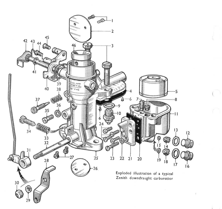
Parts lists for these carburetters can be supplied on application; please give name and type of car concerned. In any query, always quote the reference letter and figures stamped on the fuel inlet boss.