


ZENITH CARBURETTERS
SERVICE BULLETIN
SERIES 30 VIG
Also covers 36 & 42 VIS Models.
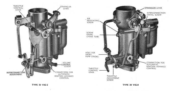
(1) PRINCIPAL FEATURES
The popular 30 m.m. VIG series of carburetters is used extensively on a wide range of modern vehicle and industrial engines of one to four litres capacity. Several patterns are made, each of the downdraught type, and the flange-hole centres on all current models are 60·3 m.m. (23/8").
Some types are fitted with fully-automatic, and others with semi-automatic, stranglers for easy starting. Similarly, the quality of the mixture for idling ("slow-running") is controlled in either of two ways. This is by regulating the amount of air admitted to the slow-running circuit, or by varying the amount of idling mixture inspired by the engine (in this case the air supply is constant).
The principal features of the various models are shown in the following table:
| Carburetter type | Normal location of throttle control | Type of strangler | Method of idle control | Notes |
|---|---|---|---|---|
| 30 VIG-5 | At side of carburetter, or at end of throttle spindle | Semi-automatic | By volume control | Replaces 30 VIG-2 and 30 VIG-3. Fuel connection 1/4" o/d pipe |
| 30 VIG-6 | At end of throttle spindle | Fully-automatic | By volume control | Fuel connection for 1/4" o/d pipe |
| 30 VIG-7 | At end of throttle spindle | Semi-automatic | By volume control | Fuel connection for 1/4" o/d pipe |
| 30 VIG-8 | At end of throttle spindle | Fully-automatic | By air regulation | Auto-ignition connection tapped 6 x 1.0 m.m. |
| 30 VIG-9 | At end of throttle spindle | Semi-automatic | By air regulation | |
| 30 VIG-10 | At end of throttle spindle | Fully-automatic | By air regulation | Auto-ignition connection tapped 7 x 1.0 m.m. |
| 30 VIG-11 | At end of throttle spindle | Semi-automatic | By volume control | Has special "follow-up" pump action |
Carburetters prior to 30 VIG-5 are obsolete, and cannot be supplied. In addition to covering the 30 VIG series of carburetters the description of the operation and comments on the adjustment are appropriate to the VIS carburetters that have been made in sizes 36 and 42 m.m.
On the VIS models the economy device is mounted on top of the float chamber cover but it operates in an identical manner to the same feature in VIG models. All VIS carburetters have air regulating screw control to idling mixture as referred to under sub-heading "Idling" on page 3.
Each of the above is fitted with a mechanically-operated accelerating pump, a depression-operated economy device which is entirely automatic, and a strangler interconnected with the throttle for fast idling. A direct-acting float mechanism controls the fuel level in the float chamber, and an automatic ignition-control connection is provided.
 Adjustments
(2) OPERATION
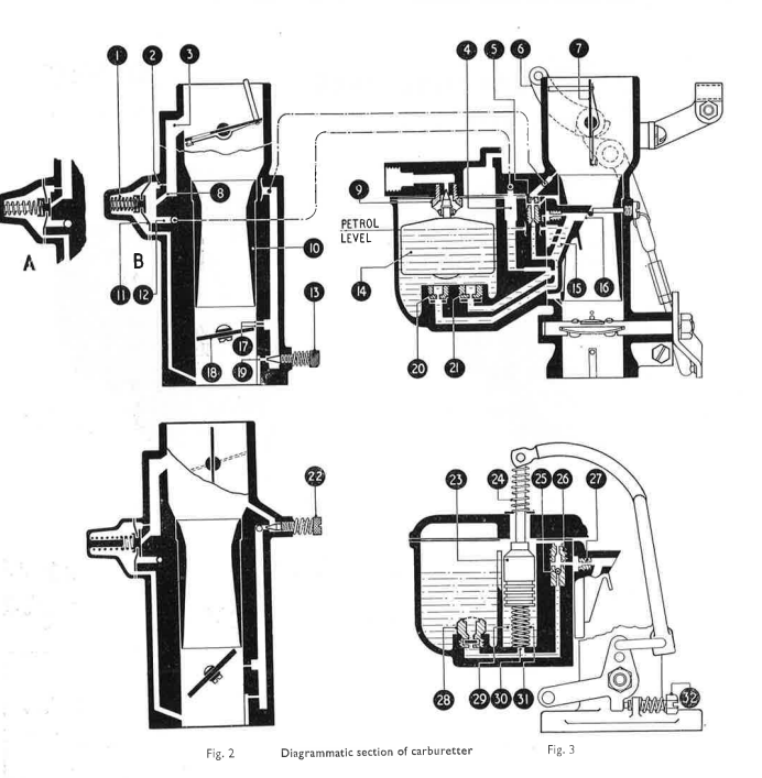
(a) Fuel is admitted at the top of the float chamber cover, then flows through the needle seating 9, past the needle and into the float chamber. As it enters, the float 14 will rise, lifting the needle and shutting off a further supply when the pre-set level is reached. As the engine consumes fuel the level drops and the float descends, allowing more petrol to enter the float chamber; this cycle of operations continues, thus automatically maintaining the correct petrol level the whole time the engine is running.
From the float chamber the petrol flows, via the main and compensating jets 20 and 21 respectively, into the emulsion block, the beak or nozzle 16 of which protrudes into the choke tube at its smallest diameter, i.e., at the area of maximum depression.
(b) Starting from cold The strangler lever 6 is operated by the choke control fitting on the dashboard. When this is pulled out the strangler flap 7 closes; at the same time, by means of a suitable mechanism—a cam in some cases and an interconnection rod in others—the throttle is automatically cracked open to provide a good fast-idle. With the ignition switched on (but without touching the accelerator pedal) the starter button is pressed and the engine turned over. Immediately it fires the speed will tend to build up, and consequently the increased depression will operate the strangler flap.
(3) TUNING
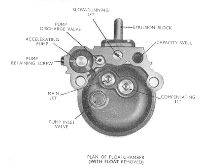
(a) A number of variables are provided in the carburetter to enable it to be tuned for the correct fuel/air ratio at all throttle openings and for all speeds and loads.
It will be fully appreciated that, where the VIG carburetter is fitted as initial equipment on a production engine, the values of the jets and other variables are fixed only after exhaustive bench and road tests have been carried out by Zenith engineers, working in collaboration with the Experimental and Road-test departments of the vehicle manufacturers. In all such cases, we recommend that no changes should be made to these standard settings—which are normally intended for operation at about sea level—until careful checks of other engine factors (ignition, tappet adjustments, etc.) are first made.
Unless otherwise stated, all the jets in the carburetter are calibrated in units of hundredths of a millimetre, and are normally available in steps of five units. A higher number denotes a larger calibration, i.e., a jet stamped 100 is a size larger than one marked 95. Half-size main and compensating jets for final tuning can be supplied to order if required; a jet marked 82 is halfway between 80 and 85.
Choke tubes have their sizes clearly marked inside, the figures showing the diameter of the restricted portion. These range in steps of one millimetre, and half sizes are not supplied.
(b) Altitude An exception to the remarks previously made about altering the standard setting arises when the carburetter is consistently used at altitudes above 5,000 feet. Owing to the rarified atmosphere it is necessary to reduce jet sizes to maintain the correct fuel/air ratio. The following changes are therefore recommended:
| Altitude | Main jet | Compensating jet |
|---|---|---|
| 5,000 to 7,000 feet | 1 size smaller | 1/2 size smaller |
| 7,000 to 10,000 feet | 1 1/2 sizes smaller | 1/2 size smaller |
| 10,000 to 15,000 feet | 2 sizes smaller | 1 size smaller |
Although no alteration is specified for heights up to 5,000 feet, when economy rather than performance is the prime consideration, we suggest trying a half-size smaller main or compensating jet above 3,500 feet. The above changes are suggested only for vehicles used at the various altitudes mentioned. None need be made where cars or trucks climb temporarily to a few thousand feet, then drop back to heights below about 2,000 feet, as in the European Alps.
(c) Variables In addition to the above-mentioned variations to the jets, further alterations to the setting can be carried out when tuning a particular engine. These are:-
Choke tube
This controls the weight of charge inspired by the engine; the size usually decided upon is the smallest that will develop maximum power.
Main jet
As in all "V" type models of the Zenith carburetter the mixture (above idling speeds) is supplied by the main and the compensating jets, both of which feed the beak of the emulsion block via the inclined passage 15. The main jet influences power and speeds at medium to large throttle openings, and its output is directly related to the depression existing at the waist of the choke tube, into which the emulsion block beak 10 protrudes. For the sake of economy, the smallest main jet which, conjointly with the compensating jet, gives maximum power and speed with a particular choke tube, should be used.
Compensating jet
As previously mentioned, the flow from the compensating jet is complementary to that of the main jet, both discharging into the emulsion block, and it is in operation at all ranges above idling speed. From the diagram it will be seen that this jet is ventilated to the atmosphere through the top of the capacity well. The function of this well is to provide a reserve of fuel during acceleration; in some cases the top is left open, and in others a tubular screw is fitted, drilled to a particular size, as referred to elsewhere in this bulletin.
As the compensating jet is vented to the air it will be realized that, although the engine depression increases, the flow from the jet is not affected to the same degree as in the case of the main jet, and it is therefore the combined discharge from both the main and compensating jets that provides the mixture best suited to the engine. Variations to the compensating jet will have less influence on the mixture strength than alterations to the main jet, affecting acceleration and low-speed pulling.
Slow-running jet
This is a calibrated jet 5 which supplies a measured quantity of fuel to the slow-running hole 19 on the engine side of the throttle, and also to the progression hole(s) 17 at the throttle edge. It is usually unnecessary to alter the size of the jet from that fitted by the makers of the vehicle. Half-sizes are not supplied.
Pump jet
This is the small calibrated jet 27, which screws into the back of the emulsion block immediately behind the beak of the latter. Access to it is obtained by removing the emulsion block. Its purpose is to meter the amount of fuel injected into the main airstream when the accelerating pump piston is thrust down by the throttle interconnection mechanism.
Care must be taken, when removing or replacing this jet, not to damage the threads or the slot in the head. Available in steps of ten units from 50 to 90 inclusive, half-sizes are not supplied. Sizes below 50 are liable to become choked. If, therefore, it is desired to reduce the discharge from the jet a modified pump inlet valve can be supplied. In this, a small leak is provided in the valve, so that some of the fuel can be returned to the float chamber when the pump is operated.
Screw over capacity well
Variations to the size of the hole in this screw will affect the mixture strength, but in a rather different manner to an alteration in the size of main or compensating jets. A small hole will enrich the mixture when the economy valve 11 is open, but will have little influence when the valve is closed and the extent of ventilation to the capacity well is controlled solely by the small permanent airbleed 2.
Needle valve and seating
This is a calibrated unit, and the diameter of the seating hole, in millimetres, is stamped on one side of the hexagonal body. The correct size depends on the pressure in the fuel line, and the capacity and output of the motor.
(4) GENERAL
(a) It must not be forgotten that several other factors, apart from the carburetter, affect performance and consumption. It is therefore advisable to check plugs, distributor and ignition generally before making carburetter adjustments. See that all manifold joints are tight, and that the compression in all cylinders is good.
As well as the jets and the other variables described above which may, if required, be changed when the carburetter is in service, other features (also part of the setting) are built into the carburetter during manufacture. These concern the sizes and positions of various drillings, strength of springs, etc., and are the features in the design which permit the carburetter to be precisely suited to the engine on which it is fitted. (It is these drillings which prevent the substitution of one 30 VIG model for another by merely changing the choke tube or jets.) However, when the values of the variables in the carburetter have been settled, the mixture strength at different speeds and loads will be constant, assuming that the jets and channels are clean and the instrument is in a sound mechanical condition.
In cases where faulty carburation is suspected, first check that the sizes of the choke tube, jets, needle and seating, etc., conform to those given in the setting specification for the engine concerned. While it is important to see that the correct numbers are stamped on the jets, the possibility that they may have been tampered with, or that careless cleaning has affected the flow of petrol or air through a jet or air bleed, should not be overlooked. If any signs of interference with them are found, new parts should be fitted.
It must be appreciated that, after years of service, the moving parts in the carburetter will inevitably wear. If the vehicle is some years old, and the carburetter is the one originally fitted, this wear - which can affect all aspects of carburation - can have a considerable bearing on some of the typical troubles mentioned below. We therefore strongly recommend that, when an engine needs a major overhaul, the worn carburetter is replaced by a new unit, so that the utmost benefit may be obtained when the engine is restored to its original condition.
When making a general check on carburation, the following notes will be found helpful.
(b) Difficult starting from cold Ensure there is sufficient petrol in the float chamber, and that it is replenished within a few seconds of turning the engine over by the starter, or by the operation of the hand primer on the fuel pump. Occasionally there is a tendency for the needle to stick on its seating owing to the formation of a gummy deposit from petrol or additives, thus preventing the entry of fresh petrol. In such a case remove the needle and seating and rinse well in methylated spirit; this will dissolve the deposit, and allow the needle to drop freely by its own weight.
Check that the strangler flap closes completely when the dashboard control is operated. In the fully-automatic stranglers fitted to the 30 VIG-6, -8 and -10 models the flap is not rigidly controlled by the strangler spindle but is operated by the tension of a coil spring. If, therefore, the spindle is bent or the bearings are stiff, either of these could prevent the flap closing fully. Another cause of the trouble could result by over-tightening the air cleaner connection; this can be checked by slackening the clamp to see if the flap operates freely.
The strangler/throttle interconnection is provided to open the throttle beyond the normal idling position when the strangler is fully closed. The correct gap between the edge of the throttle and the side of the throttle bore at the slow-running outlet can be set by means of the shank of a drill. Alternatively, it may be adjusted by the throttle stop screw, as described on page 4, measured in half-turns (i.e., 180°) from the fully closed position. Details of both are given under the heading of "Fast-Idle Interconnection Setting" on the Zenith Service Bulletin for the vehicle concerned. If the above points have been checked, and ignition and engine generally are in good order, the interconnection adjustment should be slightly increased.
(c) Difficult starting when hot This trouble is usually due to over-richness, the most common cause being flooding. In such a case, check that the needle and seating assembly is the correct size, is thoroughly clean and is screwed home tightly. If worn, it should be renewed. Check the fuel level (see paragraph 2 f); examine the float to ensure it is not punctured and that it is the right way up.
Should it be found that flooding persists (evident by petrol dripping from the beak of the emulsion block when the throttle is in the idling position, or within a few seconds after stopping the engine) after a new needle and seating assembly has been fitted, check the fuel pump pressure and, if necessary, have it reduced. In normal circumstances this pressure should not exceed 2 1/2 lb./sq. in. at cut-off, i.e., at the instant of switching off the engine.
Where difficulty in hot-starting is experienced, it can usually be overcome by opening the throttle gently to its fully or near-fully open position, then turning the engine over by the starter with the ignition switched off to clear the over-rich condition. Then return the throttle to the normal slow-running position, switch on and rotate the engine with the starter, when it should then fire and run.
(d) Erratic slow-running, or stalling on deceleration See that the slow-running jet 5 is perfectly clean, and is screwed home flush with, or a little below, the top surface of the float chamber. Check that the gasket over the float chamber is in good condition, and that the two bolts securing the float chamber are evenly tightened when replaced. Ensure that the slow-running outlet hole and the progression hole(s) in the throttle barrel are clear and not carboned up to form a restriction.
Due to excessive or uneven tightening of the nuts when the carburetter is fitted to the induction manifold, the flange sometimes becomes bowed, thus admitting air at this joint. In such a case, the flange face should be carefully filed flat, and a new gasket used for making the joint. Reasonable force only should be employed when bolting the carburetter down.
Inspect the tapered end of the volume control screw 13 (or air-regulating screw 22 where fitted) and see that it is in good condition. If it has been forced into its seating several times a parallel portion will be formed on the taper, rendering it useless. Replace the screw with a new one. See that the spring on the screw is "live", and prevents the screw vibrating out of adjustment.
The throttle stop screw 32 determines the idling speed, and the volume control or air-regulating screw controls the mixture strength. Set the former to give an idle speed in the region of 500 r.p.m., then adjust the volume control or air-regulating screw so that the engine idles evenly at this speed, with no tendency to stall when the throttle is suddenly closed. At the same time, clean progressive acceleration should result when the throttle is opened gently from the idle position on to the progression hole(s). With the mixture correctly set, it may be necessary to readjust the throttle stop screw slightly to give a satisfactory idling speed.
(e) High fuel consumption The carburetter is frequently blamed for this when the trouble is really due to one or more other causes, i.e., a leak in the petrol system, fuel pump pressure too high, engine stiff or in poor condition, brakes binding, retarded ignition, restriction of the carburetter air supply because of a faulty strangler or a choked air cleaner, etc. Furthermore, rough estimates can be very misleading, and the fuel consumption should be checked over, say, a hundred miles, to see if it is excessive or not. Short journeys and town work mean increased consumption, and the average figures quoted by the car manufacturers are for country running on give-and-take roads with normal loads, driving at 30/35 m.p.h.
If the consumption is found to be excessive, smaller main and/or compensating jets should be tried. One can be altered without affecting the other, and therefore the effect of changing one jet at a time should be tried. Should the fuel pump pressure be too high, it will not be found possible to obtain a smooth tick-over no matter how the volume control or air-regulating screws are set, and petrol fumes will be noticeable when the car is running downhill. The remedy is to fit a smaller needle and seating, but if this causes restriction to the petrol supply at high speed the pump itself should be suitably adjusted.
Check that the carburetter has the standard setting of jets and air bleeds fitted, and that all holes and passages in the instrument are clear. See that the strangler flap opens completely when the dash control is released or pushed in.
Dismantle the economy device to make sure the diaphragm material is sound and intact, also that the gaskets (one on each side of the diaphragm) are in position and are in good condition. When re-assembling the economy diaphragm, etc., see that the spring beneath the cover is in position and is located squarely in the recess of the metal cup in the centre of the diaphragm. Take care to tighten evenly and fully the screws securing the cover: any leakage at the joint will affect the degree of depression necessary to overcome the spring which normally holds the diaphragm valve in the closed position.
Remove the ball valve 25 that screws into the top face of the float chamber, to ensure that the ball moves up and down quite freely, and will drop by its own weight. Sediment or gum might cause the ball to stick on the upper seating; in this event, petrol will issue from the pump jet at all times and affect consumption adversely, and the valve should be rinsed in methylated spirit. (It will be appreciated that, when the ball drops, any depression over the pump jet will merely admit a limited amount of air from the uncovered air bleed at the top of the valve).
Examine the gasket under the emulsion block and check that it is in good condition, also see that the screws securing the block are tightened evenly and firmly to prevent any possibility of leakage.
(f) Poor acceleration Check that the pump piston moves freely in its cylinder, and returns to the upper position by the spring fitted beneath the piston. Having removed the piston to make sure the cylinder is clean, extract the non-return valve in the base of the float chamber and wash it thoroughly in clean petrol or methylated spirit. This will ensure it will close effectively on the downward movement of the pump piston.
Remove the pump jet and see it is perfectly clean, and will give an unbroken stream of petrol from the orifice when the pump piston is pushed down. If the pump link is in the inner or "summer" hole, transfer it to the outer hole or, in the case of the 30 VIG-11, turn the pump block to provide the maximum stroke. (See paragraph 2 (d). Check the economy device as described in paragraph 2 (e).
In time, carburetter wear will result in reduced output from the pump and affect acceleration and slow-running adversely. Flat spots or hesitation on progressive opening can generally be banished by careful adjustment of the slow-running mixture, after checking that the progression holes in the throttle barrel are unobstructed.
(g) Loss of power Check that the holes and passages in the emulsion block are clear, and that the throttle opens fully. Larger main and compensating jets may be tried to see if increasing the strength of the mixture will improve maximum speed and power. In cases where an engine has been modified with a view to increasing the power output, a larger choke tube with correspondingly bigger jets should be tried.
If advised of modifications made to an engine, we can usually suggest an alternative setting which will serve as a basis for tests to tune the carburetter to suit them. These remarks apply equally to twin or multiple carburetter conversions and we shall be pleased to give owners the benefit of our experience on similar installations.
Parts lists for these carburetters can be supplied on application; please give the name and type of the vehicle concerned. In any query, always quote the reference letter and figures stamped on the fuel inlet boss.
LINKS:
- Rebuild kit - For a Single 30 VIG Carburettor
- Service Kit - For a Single 30 VIG Carburettor