


SOLEX CARBURETTERS SERVICE BULLETIN
SERIES B.32 PAIA B.32 PAIA-2 DIAGRAMMATIC SECTION
OPERATION
ZERO PROGRESSIVE STARTER.
Operation of the starter is by rotation of the starter disc valve (Dd), which is connected to the dashboard control by means of a flexible cable and lever. When starting from cold the dashboard control is pulled fully out (Full Rich Position) thus aligning a slot in the starter valve (Dd) with the main feed channel from the starter well. The depression created below the throttle valve on operating the starter motor causes petrol to discharge from the starter jet (Gs) into the starter well, where it is emulsified by air passing through small holes in the starter emulsion tube, the resultant mixture then passing into the inlet manifold via the main outlet port.
At the moment of the engine firing and running an increase in manifold depression, consequent upon the increase in engine revolutions will cause the piston (Pn) to move downward, thus allowing air to pass from the air-intake to the starting system for the dual purpose of weakening the mixture and allowing the engine to develop power.
When the engine has run for a few seconds the dashboard control is pushed in approximately half-way and, if necessary, the vehicle can be driven away without difficulty although the engine is still relatively cold, due to the partly open throttle-valve creating depression and consequently a mixture discharge at a point just below the choke-tube. As the engine warms up the dashboard control is moved gradually inward, thereby permitting the starter valve to both progressively weaken the mixture and provide a range of fast-idle speeds; the speeds gradually decreasing as the control approaches the fully OFF position. When the dashboard control is pushed fully home the starter unit will have been put completely out of action by the closure of the various air and petrol orifices.
THE IDLING CIRCUIT.
This supplies through orifice (io) mixture required for idling when the engine is warm. It also provides, through by-pass (Bp), the mixture required as the throttle is first opened, but before it opens enough for the main spraying orifice (Oo) to begin to discharge.
The circuit is as follows: Petrol is supplied from the reserve well (v) and metered by the pilot jet (g). Emulsifying air is metered by a fixed orifice sited directly above the pilot jet. When idling additional air passes through by-pass (Bp) and the volume of this mixture is controlled by screw (W). On leaving idling orifice (io) the mixture is further emulsified by air passing round the throttle (V), the latter being held slightly open by an adjustment screw. As the throttle is opened engine depression is directed to the by-pass orifice (Bp) which discharges additional mixture to meet engine requirements until the throttle (V) has been opened sufficiently for the main spraying system to come into operation.
MAIN SPRAYING SYSTEM.
This is in two parts, namely, primary and secondary circuits. As the throttle (V) is opened further and air speed through the venturi or choke-tube (K) rises, depression acting on spraying orifices (Oo) brings the main spraying circuit (primary) into operation. Under this condition petrol flows from the float-chamber and is metered by the main jet (Gg) before passing into the main spraying well where it mixes with air metered by the correction jet (a); the air entering the petrol stream by means of small holes in the emulsion tube. From the main well the mixture finally discharges through orifices (Oo) into the main air stream. As engine speed increases the petrol level in the well (Mw) drops and uncovers the remaining holes in the emulsion tube, thus allowing a greater quantity of air to enter the petrol stream to correct the output from the main jet according to engine speed and load.
The secondary main spraying circuit comes into operation when depression in the waist of the primary choke-tube reaches a certain value and opens throttle (V2) via the depression unit (Dc) and connecting rod. The main jet, air correction jet and emulsion tube then follow the pattern of operation as described for the primary circuit. During the initial opening stages of throttle (V2) a discharge of mixture takes place from the by-pass orifice (similar to Bp-primary circuit).
THE ACCELERATING PUMP.
The accelerating pump is mechanical in operation and consists mainly of pump membrane (M), pump spring (r), pump lever (Pl) and an actuating rod, the latter item being the connecting link between the primary throttle spindle and lever. On depressing the accelerator pedal the movement of the actuating rod and lever displaces the pump membrane (M), and in so doing forces petrol through the calibrated pump injector tube (i) into the main air stream, thereby ensuring a condition of rapid, smooth acceleration. Non-return valve (Ci) prevents the petrol returning to the float chamber when the membrane (M) is displaced.
PETROL LEVEL.
The level of fuel in the float chamber is controlled by the slight rise and fall of the float, closing or opening the needle valve (Nv) to cut off or admit petrol from the fuel pump as required. The design of the mechanism ensures complete stability of the predetermined level, thus eliminating all need for routine checking. The float assembly, however, must be replaced immediately in the event of damage, in order to maintain the correct fuel level.
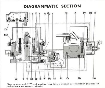
Main spraying well (Mw) and emulsion tube (s) are identical (for illustration purposes) on both primary and secondary circuits.
STARTING PROCEDURE
INITIAL STARTING
Place mixture control in full-rich position. Switch on ignition, but do not touch the accelerator pedal whilst attempting to start the engine. The engine will start immediately the starter motor is operated and as soon as the engine gathers speed, move the mixture control in approximately one-quarter of its travel. After this process it is recommended to drive away at a moderate speed (to allow engine lubricant to distribute), the mixture control being progressively moved to the "off" position as the engine warms up. Do not forget to move the mixture control to the full "off" position as soon as possible in order to avoid unnecessary fuel wastage and high consumption.
HOT RE-STARTING
Do not use the mixture control if the car has only been left for a short time and the engine is still reasonably warm. If the engine and ambient temperatures are high and it does not start at once, depress the accelerator pedal about one-third of its travel maintaining this position until the engine fires and runs. Do not pump the accelerator pedal.
SETTING THE IDLING
Having made sure that there is no undue wear in the throttle spindle and bearings, that flange joints are tight, distributor and spark plug points are clean and set to Manufacturers' recommendations, the following adjustments are made with the engine warmed up:-
- Set the throttle (slow-running adjustment) screw until the idling speed is approximately 850 r.p.m.
- Unscrew the volume control screw (W) until the engine begins to hunt.
- Screw it in again until the hunting disappears and the engine idles smoothly.
- If the engine speed has risen then reset the slow running screw to bring it back to about 850 r.p.m.
- This may cause a slight resumption of hunting. If so, gently screw in the volume control screw (W) until idling is perfect.
LINKS: