AMAL CARBURETTERS
HINTS AND TIPS
TYPE 379 & TYPE 391
As used on Motor Assisted Pedal Cycles, Agricultural and Stationary Engines.
(1) FAULTY MIXTURES, ITS SIGNS AND CAUSES
There are only two possible faults in carburation, either richness or weakness of mixture.
| Richness - Indications of: | Weakness - Indications of: |
|---|---|
| Black smoke in exhaust. | Spitting back in carburetter. |
| Petrol spraying out of carburetter. | Erratic slow running. |
| Four strokes, eight-stroking. | Overheating. |
| Two strokes, four-strokes. | Poor acceleration. |
| Heavy, lumpy running. | The engine goes better if: The throttle valve is not wide open, or if the starting chamber is kept supplied with fuel. |
| Sparking plug sooty. |
If richness or weakness is present, check if caused by:
- Petrol feed. Check that the main jet, needle jet and passages are clear and that there is ample flow of fuel. Ensure that the air vent from air intake to float chamber is unobstructed. Check there is no flooding of the float chamber.
- Air leaks. At the connection of the carburetter to the engine.
- Defective or worn parts. As a loose fitting throttle valve, worn needle jet, or loose needle jet or main jet.
- Air filter elements obstructed.
- Carburetter not correctly adjusted. See Adjustment or Tuning below.
(2) PARTS WITH WHICH THE CARBURETTER IS ADJUSTED OR TUNED
(See illustration of parts 3, 4, 5, 7)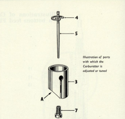
The Main Jet (7). Each main jet is calibrated and numbered, so that its exact discharge is known. Two main jets of the same number are alike, never reamer a main jet out, get another one of the right size, the bigger the number the bigger the flow, the numbers varying, for example, 20, 22, 25, 27, 30, 32.
The Throttle Valve (3). The slope at (A) is called the cutaway, and its number is stamped on the bottom. Throttle valves can be had with different cutaways, the bigger the cutaway and number, the weaker the mixture produced for small throttle openings.
The Jet Needle (5). The jet needle is positioned in the throttle valve by the jet needle clip (4). The top of the jet needle is grooved and by springing the clip off and springing it on again in another groove the position of the jet needle in the throttle valve is altered, either being raised or lowered.
(3) ADJUSTMENT OR TUNING OF CARBURETTER
A certain amount of adjustment is provided for on the carburetter to ensure that a correct mixture is obtained. The correct mixture is one that is neither too rich nor too weak. See that there are no faults as outlined in "Maintenance" as these would affect the correct functioning and adjustment of the carburetter. Check that the ignition, timing, etc., is functioning correctly.
Carburetters as supplied by the makers for fitting to specific machines should under normal conditions only require adjustment of the position of the jet needle (5) to ensure best general running with maximum fuel economy, the jet needle being raised if the mixture appears to be weak and lowered if the mixture is rich.
For special conditions or adaptations, or where it is suspected that the carburetter may have had an unsuitable throttle valve or main jet substituted, as these parts vary according to engine requirements, it will be necessary to completely re-tune the carburetter. See "Complete Tuning of Carburetter."
Complete Tuning of Carburetter
To remedy weakness or richness, proceed as follows:
| Position of Throttle | To cure richness | To cure weakness |
|---|---|---|
| At ¾ to full throttle. | Fit smaller main jet. | Fit larger main jet. |
| At ¼ to ¾ open, as for general running. | Lower jet needle. | Raise jet needle. |
| Up to ¼ opening, as for idling and light running. | Fit throttle valve with larger cutaway. | Fit throttle valve with smaller cutaway. |
Finally, if any alteration has been made to the throttle valve cutaway, it may be necessary to alter the jet needle position again, putting in a throttle valve of smaller cutaway may require the jet needle lowering by a groove, and alternatively a larger cutaway may necessitate raising the jet needle.
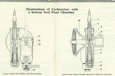
(4) HOW CARBURETTER WORKS
The float chamber maintains a constant level of fuel at the jet and cuts off the supply when the engine stops. On fuel flowing from the float chamber the float (13) falls, and its needle (12) coming away from its seating allows fresh fuel to enter. Depression caused by movement of the engine piston causes, via the throttle opening, air to flow into the main air intake (10) and fuel to flow through the needle jet (6) into the cross bore and mix with the incoming air forming a fuel/air mixture.
Correct fuel/air proportions for various throttle openings are governed by:
- The size of the main jet (7) which controls the amount of fuel fed to the needle jet (6) at ¾ to full open throttle.
- The taper of the jet needle (5) which, operating in the needle jet (6), controls the amount of fuel fed at lesser openings.
- The parallel portion of the jet needle (5) which, on entering the bore of the needle jet (6), and in conjunction with the amount of cutaway on the throttle valve (3), controls the idling mixture.
A Strangler shutter fitted to the main air intake (10) when closed prevents air flowing into the intake thus increasing the flow of fuel for easy starting when the engine is cold.
(5) STARTING INSTRUCTIONS
Follow the Engine Maker's instructions regarding recommendations about type of fuel or mixture to be used.
Starting engine from cold. Close strangler shutter, set throttle valve about ¼ open, start engine and when it commences firing open the strangler shutter and throttle down to an idling speed. If on opening the strangler the engine begins to falter, partly close again until engine runs regularly, then fully open strangler and leave open.
Starting when engine is warm. The strangler shutter should be in its fully open position, the throttle should be slightly opened and the engine started.
(6) MAINTENANCE
Removing and fixing carburetter
If the carburetter is removed from the induction pipe, see that on re-fixing it is pushed right home on the pipe before locking the clip. Never fit the carburetter to a pipe on which it is slack, nor ever drive it on to a tight one. The carburetter should be a good push fit on to the inlet pipe, and should be pushed on true with a screwing motion, after having put a little oil on the pipe. Erratic slow running can be caused if there are air leaks at the point of attachment of the carburetter to the cylinder.
Dismantling when inspecting or tuning
The float chamber, float or its needle may be inspected by removing the float chamber cover (11), which is secured by two screws. In the case of a top feed carburetter the float and needle can then be lifted out; if carburetter is a bottom feed the banjo bolt (14) must be removed and then the float needle is removed by pushing the needle downwards through the float and extracting it through the needle seating in the base of the float chamber; on re-assembling see that the spring bow on the float top engages with the groove in the needle. Ensure when replacing the cover that the joint washer is undamaged.
Throttle Valve Removal
The throttle valve complete with jet needle and attached to the cable can be withdrawn from the carburetter after the knurled mixing chamber top (2) has been unscrewed. To separate the throttle valve and jet needle from the cable release the cable at the control end and push the inner cable forward until the nipple in the throttle valve clears its hole, then withdraw the cable through the slot in the throttle valve, the nipple passing through the hole at the extreme end of the slot. On re-assembling pass the nipple through this hole via the inside of the throttle valve, ensure that the portion of the jet needle clip (4) that falls in towards the jet needle is opposite the cable slot in the throttle valve, and then draw the cable forward until the nipple will pass over the end of the throttle valve and sink into its hole. On putting back this throttle valve assembly into the body, see that the key in the carburetter body engages the key-way opposite the cable slot in the throttle valve, and that the jet needle is entering the needle jet, before attempting to push the assembly home.
Main Jet Access
Access to the main jet is by removing the main jet cover nut (9) and withdrawing the filter gauze (8). When replacing the main jet take care not to over-tighten.
Filter Gauze
A filter gauze (8), which is a push fit over the main jet and needle jet, should be periodically examined and cleaned if necessary by washing in clean petrol.
Fuel Feed
Ensure that the fuel tap and pipe are kept clear.
Float Chamber
Ensure that there is no continual flooding of the float chamber.
Excessive Fuel Consumption
May be due to continual flooding of the float chamber, check that the float needle is not worn or bent, that the float is not leaking, that no impurities have got into the float chamber and lodged on the float needle seating. Nearly all flooding with new machines is due to impurities (grit, fluff, etc.) in the fuel tank, so clean out the float chamber periodically until the trouble ceases. If the trouble persists, the fuel tank may be drained, swilled out, etc.
Cable Controls
See that the cable control fully opens and closes the throttle valve (3); a cable adjuster (1) with locknut is provided in the top of the carburetter and can be adjusted until correct movement is obtained.
Air Filter Elements
Should be kept free from obstruction. Periodically these should be removed and washed in petrol, then dipped in thin oil and allowed to drain, and replaced in carburetter.